Robot Arena III

Robot Arena III

Not enough ratings
Bot Lab Basics
By ra3bld and 1 collaborators
This guide provides an introduction to the bot lab and its many features. Haven’t created a robot in the bot lab? After reading thru this guide, you should be able to easily create your own precision engineered, bot stomping, metal grinding, automaton of destruction. Enjoy!
   
Award
Favorite
Favorited
Unfavorite
Overview


The Bot Lab allows you to build and test your robot prior to engaging in single or multiplayer robotic combat. Upon entering the Lab, you will be presented with a 3D view of your robot and a handful of menu items on the left. The menu system at the left is called the Toolbox, and consists of the following:
  • Build
  • Paint Shop
  • Test
  • Workshop
  • Summary
  • Lab Manual
The Build menu and its submenus provide all the functionality you need to create your own robot. Test provides one or more arenas within which to test your robotic creations. The Workshop provides a convenient way to upload your robot to the Steam Workshop to share with other players. The Summary allows you to review your robots win / loss record and to take a glamour shot of your robot. The Lab Manual is most likely a pointer to this guide, yes, the one you’re reading right now.

As you select different menu items in the Toolbox, the Bot Lab ‘mode’ may change depending on the menu item selected. Different modes allow you access to certain features primarily related to robot construction. Each of these modes will be described further below.

Regardless of which mode you find yourself in, you can typically rotate your robot by simply pressing down on the right mouse button and moving your mouse. You can zoom in and out with the mouse scroll wheel.

The Bot Information Panel shows your bots mass, power, and air capacity.

Build Overview


There are several different build modes in the Bot Lab that provide specific functionality in building your robot. These modes can be selected from the Build Menu and are shown below. At a high level these modes allow you to create and manipulate your bot’s chassis; add and manipulate components on your bot; and finally “wire up” input controls for those components that are controllable (i.e. motors). Specifically, the build modes are:
  • Chassis Extrude
  • Chassis Layers
  • Chassis Prebuilts
  • Armor
  • Components
  • Controls
We will now explore each one of these modes in detail.
Build - Chassis Extrude
If you’ve played Robot Arena 2 then this chassis build mode should be somewhat familiar to you. Before we jump into the specifics of this mode, a few things to note about your Bot’s chassis.

The chassis is the main component and foundation of your robot. The bot’s chassis consists of 5 layers of vertices. You can choose to edit only 3 layers of vertices or all 5 layers. The default is to edit all 5 layers, and is there to give players ultimate control over how their robot’s chassis looks structurally. For those players that don’t wish to have that level of control, the player can select the Three Layers option in the Chassis Tools panel to edit only 3 layers of vertices instead of all five. Your bot still has 5 layers, however, the mid-bottom and mid-top layers will be interpolated from the other vertex data. You will have less control over how your bot’s chassis looks, but this will reduce the number of layer vertices to be changed for those players who don’t require that fine level of control for the robot they are building.

When the player selects this mode, the 3D view will change to a top down view of the lab so that the player can begin laying out the vertices for their robot’s baseplate. Use the mouse to position your first vertex and click the left mouse button to place it. Continue placing vertices until you are satisfied with your baseplate outline and close out the baseplate polygon by selecting the original starting vertex. The extrude button should now highlight. See the image below.

Figure: Layout baseplate for extrusion


If you aren’t happy with the outline, you can select a vertex and move it around to a different position. You can also click the “Reset” button and that will allow you to start over with laying out your baseplate vertices. Once happy with your baseplate, click the “Extrude” button and your bot will be extruded out in 3D and you will be placed back into a 3D perspective view. If for some reason your bot doesn’t successfully extrude, you’ll need to start again, as that specific baseplate design breaks the chassis validation rules.

You can continue to edit the layer vertices in this mode but it is recommended that you switch to the Chassis Layers mode to edit vertices.
Build - Chassis Layers
The Chassis Layers mode allows you to easily edit your bot’s vertices. The Toolbox menu will dynamically change based upon how many vertex layers you’ve chosen to edit, three or five. As mentioned previously, that can be selected from the Chassis Tools Panel. Note that there is a Snap On/Off option in the Chassis Tools Panel that you can toggle. This option will snap the vertex to the grid or allow you to freely move the selected vertex in its vertical plane.


To select a vertex to move, simply move your mouse over the vertex of interest, and click on it with the left mouse button. The vertex will highlight and you can drag it by using the mouse. When you’re happy with the location release the mouse button. Note that the selected vertex and surrounding vertices have x,y,z panels (Vertex Panels) that show the coordinate locations.

You can also select a vertex on a specific layer using the layer selection menu items on the Toolbox. In addition, for each layer, you can scale the entire set of vertices using the Scale Slider, and you can adjust the height for the layer by using the Height Slider. See the figure in this section for where these items are located.

Finally, as in all modes where you can make adjustments to your robot, the “Save Bot” button will appear when you’ve made changes to your robot. Click that to make sure you don’t lose any changes you’ve made.
Build - Chassis Prebuilts
This Build Mode allows you to select a pre-made N-sided polyhedron for your bot’s chassis. This is for convenience and for those who don’t want to use the Extrusion Build Mode to create their chassis. Simply use the left mouse button to click on a Chassis Prebuilt to change out your current chassis. Once you’re satisfied with the chassis, you can edit the individual vertices by going into the Chassis Layers Mode.

Build - Armor


This section allows you to select the armor for your robot. If you’ve already started to add “Paint” to your robot you may not notice a visual change here, but this does impact the weight and damage resistance of your robot. The main tradeoff for armor is between weight and strength. The armor types can be seen in the image for this section and in the table below. The table below gives some insight into the attributes of the different armor types.

Armor Type
Description
Plastic
Light weight and durable. Perfect for small bots that move fast.
Aluminium
Protection for the average weight bot.
Titanium
Tough plated armor that will help you last the fight.
Steel
This armor will take damage well and allow you to keep fighting.
Cardboard
When the budget is so low, you end up using the shipping container.
Wood
Found some scrap wood out back. Looks functional to me.
Carbon Fiber
Light,stiff, low thermal tolerance. Great for bikes and aircraft, why not use it for your bots.
Fiberglass
Light but not as stiff as Carbon Fiber. However it being less brittle makes it great for complex shapes.
Polymer
Ploymers are light, strong and flexible. Great for protecting you and your bot.
Build - Components
There are more than 100 components that you can pick from to add to your robot. Components fall into a number of main categories including: Power, Mechanics, Mounts, Wheels, Weapons, and Extras. This guide will cover the basics of adding and manipulating components, but for a detailed look, please see the corresponding Bot Lab Components Guide located at: <<insert link here>>.

In order to get your bot moving, you need to add power, a drive mechanism, such as one or more motors or power steering units, and you need to “wire up” these components to inputs from the keyboard, mouse or gamepad.


To select a component on your robot simply move the mouse cursor over the component of interest and click the left mouse button. Once a component is selected you will have a number of options including: translating the component within the vertical plane it sits in; moving the component up and down (i.e. changing the vertical plane that it resides within); rotating the component around the vertical axis; selecting from a number of attach points; and, re-attaching the component (for components that can be attached to the chassis) to the chassis. See the accompanying figure for more information.


To add a component, you simply select the component you wish to add from the component leaf menu items in the Toolbox Panel. Some components may be directly attached to the robot’s chassis, while other components can only be attached to an Attach Point of a component already added to the robot. For components that require a base component to be already attached, you will get a message box letting you know that you can’t yet attach that component, if there are not attach points available. Otherwise you will see a number of available attach points to which you can attach your component to.


It’s important to note that there’s a hierarchical nature to component attachment in the Bot Lab. So for instance, if I select a component that is the parent of a number of child components, rotating that component will result in the rotation of the entire subassembly. This is true for translation and other related operations that the user may wish to make to the component and its children. This feature is hierarchical in nature.

Some components have properties that you can adjust, and if you are familiar with Robot Arena 2, some of these properties will seem familiar. For instance, the DDT Burst Motor has a Start Angle and Angle Offset properties. These are exposed to the player so that they can be adjusted in the Bot Lab. Explore this property and others as you add components to your robot.
Build - Controls
This Build Mode allows you to map inputs from the keyboard, mouse or gamepad for components that are “controllable”. Not all components are controllable, but this mode allows you to hook up those that are.

For components that are controllable, actions are shown in the Component Actions section of the Components Panel as shown in the image below. For instance, the DDT Burst Motor has an action called “Fire” that can be “wired up” by pressing the “Wire” button next to the “Fire” action. Once pressed, the application will start listening for the next input from any of the attached input devices. Select an input that you wish to use to control this action of the component by pressing the respective key or button on the keyboard, mouse or gamepad. That input will then be mapped and shown in the Action Mappings section of the Components Panel.


The player should note that more than one input can be mapped to the same action and that the same input can be mapped to multiple actions.
Build - Paint Shop
The Paint Shop allows you to go in and customize your robot visually by adding Skins or Decals. You can “paint” the surfaces (top, middle and bottom) of your robot by selecting the surface and adding one or more paint layers.

To add a paint layer, simply click the ‘+’ button to add a new layer. Once a layer is added you can select an image, a skin or a decal, by clicking the ‘Image’ button. See the image below for a layout of the paint controls in the Bot Lab. You can also move a layer up or down in the stack, with the layer at the top of the list being the one on top of the paint stack. Keep this in mind when using the ‘Alpha’ tint control in the Image Controls Panel on the right of the Bot Lab interface.


The Image Control Panel lets you adjust the layer image. The controls allow you to move the image left / right / up / down; rotate it clockwise or counter-clockwise; skew the image; size the image; and tint the image as well as change the alpha channel component.

You can also show / hide the components and if you don’t like the way the layer is coming together, simply hit the ‘Reset’ button to reset the image layer back to the defaults.

To change a layer’s image, click the ‘Image’ button. This will bring up the Image Select dialog box and you can select one of the skins or decals that come with RA3, or you can select one of your own custom images by including those in the overly custom directory. See the Image Select dialog box image below.

Workshop
The Workshop allows you to upload your robot to the Steam Workshop. You can enter the name, description and category of your robot.

Summary
The Summary Mode allows you to view your robot’s win/loss record and pose / take a snap shot of your robot.

Have Fun...
Keep in mind that this game provides a platform for you to engage your imagination and explore what will work and what won’t. If at first you don’t succeed, well…, the drawing board has plenty of erasers and markers. Create, explore, and try new variations on what you know already works.
6 Comments
TimRockIt 8 Dec, 2017 @ 7:28pm 
Some important information that needs to be included.

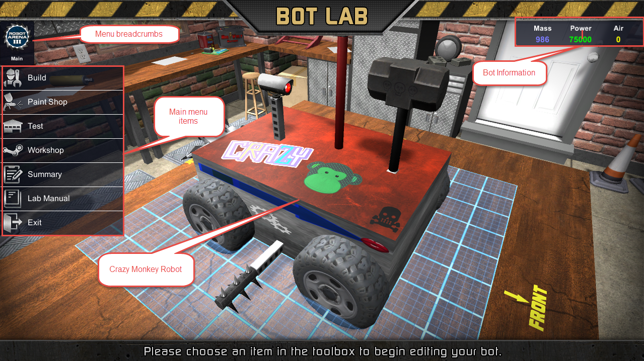
There are 4 weight classes:
1. (L)ight, less than 400 kg
2. (M)iddle, 400 - 799 kg
3. (H)eavy, 800 - 1,299 kg
4. (U)ltra, 1,300 and up

Ultra weights are NOT allowed to enter a Career Tournament. If you attempt to do so anyway, then the game is going to confiscate your illegal entry and lock it out without any warnings (search discussions on steam to learn how to recover your locked bot). Exhibition mode is where you're supposed to go for playing around with Ultra-weights.

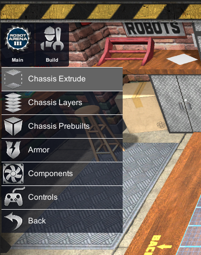
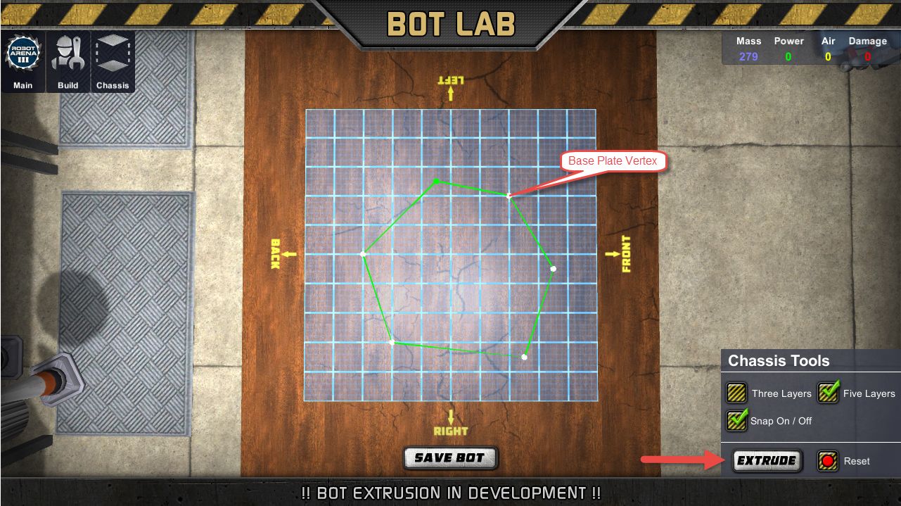
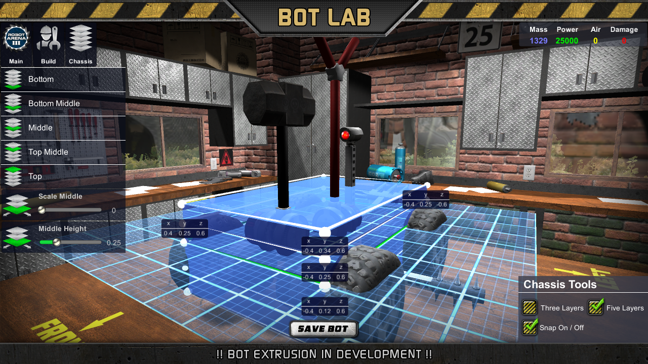
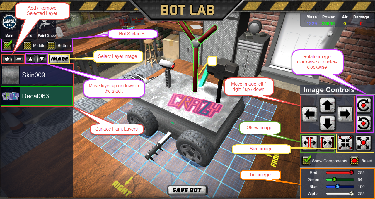
The bot lab baseplate creator will not allow you to create illegal baseplates, but you can still shape strategically placed chassis vertices into illegal configurations in the extruded layer mode of the editor as long as it's not too complex.

For advanced bot model creation you'll have to manually edit the 'bot.json' script found in the '..\Users\(profile name)\Documents\RobotArena3\Profile0\Bots\(botUUID)' location. It's not hard, but tedious.
Meyonnez 4 Jul, 2017 @ 7:49pm 
How do I make my bot small like the lucky bot? with 3 layers it's too big.
RolanDecoy 21 Jun, 2016 @ 6:54pm 
You can wire up multiple buttons for the same actions on the same components.
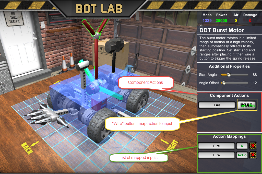
For instance, you can add W and A to tell a motor to spin clockwise for forward motion or spin to the right.
That way you can spin on a dime without forward momentum.
thyagoa 31 May, 2016 @ 11:21am 
You wire a button to each motor on the robot.

The motors I have used had 2 modes
1. Spin: it spins while you have the button pressed.
2. Turn On/Off: a button pressed makes the motor start and it stops only when you turn off by another button.


If you have 4 motors , 2 on each side, you can wire 2 on the left fot clockwise spin and two on the right for counterclockwise spin on the same button (like "W" or "S" key). It will make the robot go forward or backwards... i don't reccal it on this moment! xD


When you press the button all motors will go on and spin on the same moment, and the bot will go on riding on the test lab!
SillieBillie~ 27 May, 2016 @ 3:49am 
@camholding The power steering is normally used with 4 wheels or more. Whilst you can hook it up to turn left and right you'll still need another motor to power it forwards and backwards.
Vngd 26 May, 2016 @ 11:01am 
for the power steering unit, i dont fully unserstand the wiring, can anyone help?