Serious Sam Fusion 2017 (beta)

Serious Sam Fusion 2017 (beta)

60 ratings
TEN TIERS OF MAP MAKING: A Complex Mapping Guide
By Thanadrax and 1 collaborators
Original russian version: https://vk.com/thanacoolbunsclub?w=wall-178875804_1695

A detailed, self-made, interactive guide in the form of "ten tiers" on creating your own level in Serious Sam Fusion 2017, developed in three days by Thanadrax. Then translated and redesigned for Steam in... "around the same amount of time" by SERBoB.
The guide goes from installing the editor up to the publication of the work in the Workshop, leaving readers with sufficient knowledge of the Editor and a couple of areas of creativity adjacent to it to work independently on their projects.

Many subtle points were not included in the articles, such as sectors, mechanisms, destructions, but I hope that this will be enough for mapping endeavors.

Happy mapping! If you don't mind, spread this guide to other Sam communities so that every Serious Sam fan has the opportunity to start mapping without jumping through separate guides.
6
2
2
2
   
Award
Favorite
Favorited
Unfavorite
Greetings, curious reader!

Obviously, you came here for some knowledge – whether you’re an experienced mod-maker or a beginner.

Following guide will provide you most of the basics of the Editor for Serious Sam Fusion 2017 and even some more. This will be a long, but a very entertaining journey, dressed in Serious Sam HD TFE style.

The guide is divided in «tiers» which will enlarge gradually with the difficulty. In order to make a map, you need to master them all. Tutorial is presented not through «steps», so it’s recommended to read everything, and for the next time user may apply another sequence of actions at own discretion.

Put some music in the background, you’re definitely going to need a creative mood. And trust me, there’s nothing difficult in crafting your own projects, aside from laziness and preconceptions holding you back.
Why learn map-building on Serious Sam Fusion?
Serious Sam Fusion is a collection of the most popular (after Serious Sam Classics) Serious Sam entries used for modding – Serious Sam HD TFE & TSE, BFE and also accompanying DLCs. Creating projects in Fusion gives you access to resources and possibilities of all games at once and even more, given the extended scripting potential of Serious Sam Fusion over others. You’ll also be able to mix those resources, without having to transfer them from one game to the other. Want to shove Khnum in «The Grand Cathedral» – just drag and drop.

Additionally, mastering ten tiers of map-building not only gives you the basic knowledge of the Editor, but also paves the way to several areas, tangential to Serious Editor – modelling, level-design, game-design.

If you are not planning on delving into the Editor and SS’s Workshop, then at least give it a try out of pure curiosity – who knows what a simple «what if» can lead to.
Hall of Fame
Before we begin, let me provide you with assurances that it is totally plausible to build your own map by following this guide. And so I introduce you to...

Children of The Guide – each project is a beautiful result of hard work, carefully aided by helpful guidance from this tutorial!
https://steamhost.cn/steamcommunity_com/sharedfiles/filedetails/?id=2790682060
https://steamhost.cn/steamcommunity_com/sharedfiles/filedetails/?id=2823452420
https://steamhost.cn/steamcommunity_com/sharedfiles/filedetails/?id=2825806943
https://steamhost.cn/steamcommunity_com/sharedfiles/filedetails/?id=2836606616
https://steamhost.cn/steamcommunity_com/sharedfiles/filedetails/?id=2624816110
Rest assured, that your creations also may very well end up here in the future, it's only up to you.

Now that you're hopefully filled with determination - let's dive right in!
Tier 1.1: Preparation – Installing Serious Editor 2017
Fig. 1 – Location of the Editor

For starters, you need to obtain the game itself in Steam. Serious Sam Fusion works in a very interesting way – each new «Sam» acquired will be automatically added to Fusion’s content.
Here’s a full list:

Fig. 2 – All contents of Fusion 2017

Made it to here? Splendid! Now let’s find the Editor. Follow Figure 1 to access a pop-up window in Steam Library section, where «TOOLS» are located.

Fig.3 – Required App

Look for Serious Sam 2017 Editor in the list and install it. Its initial cover is default, but you can diversify it to motivate your future self for new feats and fails in mapping. No shame in the latter, by the way, so don’t be intimidated.
Tier 1.2: Preparation – Project
Well, it’s time to launch the Editor!

Now then, before we get to the main work allow me to give you some warnings:
  • You must have a numpad! And Fusion should run at least on medium settings on your PC;
  • Get rid of all unnecessary packages in workshop, they may affect official files, and some people may not be able to launch your map!
  • Once you become a map-builder, there’s no way back. From this point on you will perceive the game from a completely different perspective. Good or bad – it’s only up to you;
  • There are no perfect maps. Everything is subjective and creativity-based;
  • Don’t get mad if something from this guide doesn’t work on your first try. Engage curiosity, identify the problem and solve it;
  • Critique is helpful. IMMENSELY. If someone wrote you a truly negative review, take useful stuff out of it and apply it for self-improvement!
    Originally posted by NoobMaster69:
    Mod crap, author gay
  • Never stick to a «only doing this for myself» route, that’s a self-delusion. We live in a society.
Still eager to create your own map? Good. Then, as you launch the Editor, this is what you see:

Fig. 4 – Start-up window of the Editor

Here we are interested only in several sections highlighted in Figure 4:
  1. «File» tab. In it you’re going to interact with most of basic, systematic functions of the Editor – creating, saving, opening of files;
  2. «View» tab. The scourge of most self-taught beginners. If something has gone missing from your panels, refer to this tab to try and get it back;
  3. Panel that you’ll basically be spending most of your time in. More tabs will be appearing down below, for now there’s only «Entity List»;
  4. Console! Your irreplaceable friend, which will always come to your aid, give you hints, point you to an error and nag you about incorrectly tossed in materials.

Fig. 5 – Creating new level

To start working with the Editor, you need to create a new «world» - a «.wld» file. This extension is the one responsible for your level, and this will be your future project.

Click on «File», in the drop-down list choose «New», then – «World». Wait for a few moments after that – your new level will be created.

Fig. 6 – Blank field

Now you’re dealing with a blank world. Congratulations, you’ve created an empty space! That’s where our further manipulations will be taking place.

In order not to lose all this tremendous progress, I advise you to save at this point already. «Save» function (or «Save as» if you want to rename level) is located in the same «File» tab.

Hotkey for saving – CTRL + «S».

As a reminder, we’re creating a project based on Serious Sam HD. You need to maintain order in files, so as not to embarrass yourself at release with some missing files.

Croteam has a very tricky system in terms of paths, which comes down to a simple logic: HD levels should be put where all HD levels are located, and BFE levels – where all BFE levels are located. Scary, isn’t it? You’ll get why soon.

Fig. 7 – Save path
Fig. 7 – Save path

Mainly, HD levels in «Sam» are saved using the path Content/SeriousSamHD/Levels/, and then map-builder (that’s you!) should decide what to make out of the map. If it’s going to be a single map, then it should be saved in the «Z3_Other» folder and then given a name.

By the way, have you already noticed 3 different colours of files? White-blue – your files, green – mods, red – official files.

Originally posted by Thanadrax|Cream:
«Z3_Other» folder is the main folder for most of custom maps, as well as Versus and Survival maps.

If you want to make a campaign out of your map, then save it in a new directory. For example, Content/SeriousSamHD/Levels/ThirdEncounter/.

Originally posted by Thanadrax|Cream:
This way, your map pack will stand out separately, it can later be given a general name, like «Serious Sam 5».

Our project is going to be a single map.

New folder can be created using a button with an icon of a yellow folder with red asterix, highlighted in Figure 8.

Fig. 8 – Also check out the star!

To the left of this button, you can see another button with an icon of a purple star – it can make your life significantly easier, but later on that.

‘Content/SeriousSamHD/Levels/Z3_Other/Werlion.wld’ (25.80kB) saved successfully.

I named my map with a random word «Werlion». By the way, you could notice one curious thing while saving – apart from «SeriousSamHD» folder there’s also a «SeriousSamHD_TSE» folder. If you’d like to create a map based on HD TSE, then save your map in this location. Main difference – folder for single levels is called «Z5_Other», five instead of three.

So, have you saved your level? Great, but we’re not done yet.
Tier 1.3: Preparation – Controls
Now let’s get familiar with controls within the Editor.

Originally posted by Thanadrax|Cream:
Save constantly, at least once every ten minutes. Editor is a very capricious female, which will crash at the «sweetest» of moments, robbing you of your progress and self-confidence.

You can fly around the level area by clicking «Escape» and moving with WASD, as if you have «ghost» cheat enabled. Mouse wheel – adjustment of camera speed, upwards – faster, downwards – slower.

Fig.9 – Camera movementFig.9 – Camera movementFig.9 – Camera movement

If you somehow managed to lose track of yourself – press «A» on your keyboard, camera will move to a general view of the level. Considering it’s an empty space at this point, your options are scarce.

Fig.10 – Intentional mistake

While playing with parameters, I accidentally removed one vital parameter in «View» tab, which caused one of main panels in Editor to disappear. It so happens that you are, say, typing something into console or script and your keyboard accidentally slips, and your interface might get broken apart into dozen pieces.

To fix this sort of situation, you’ll need to restore parameters of the interface. To accomplish it, delete the following file, location of which is shown in Figure 11:

Fig. 11 – The guilty party

Congratulations! You have secured yourself for a foreseeable future from tantrums like «How do I restore that VERY important little panel?!?!?!».

Now, start your level anew, and it’s time to prepare it for editing.

The magic button «N» on the keyboard lets you access the «entity» list – list of map objects. It includes models, scripts, enemies and many other things. The most interesting point: while you seem to be in an empty space, there’s already one entity present – the most important one, «WorldInfo». It is responsible for global parameters of your world.

Strongly recommend you to memorize this button, as it allows you to find certain objects very easily.

Fig. 12 – Entity list

By double-clicking on this entity, you select it in the world itself. Parameters of the entity are located in the left panel. (If not, then head to «View» tab and add checkboxes «Tools» and «Entity»!)

Fig.13 – New tabs
Fig.13 – New tabs

Make sure that tabs «Tools» and «Entity» appear beside «Entity List». They are the foundation of your further adventure.

Fig.14 – «Game title» file

The current title of the level is «SeriousSam2017» - default title that is used nowhere. Something of a blank. What we’re doing is creating a level based on parameters of Serious Sam HD TFE, and Fusion is a multi-tasking thingy, capable of handling both BFE and HD. So, click on the «Game title» file.

In the drop-down list there is a «Browse» option – it lets you select a different title. But where to look for them? The answer is right in front of you.

There’s another option – «Locate». It differs from «Browse» in that it initially opens the folder, in which the selected file is located. «SeriousSam2017.gtitle» is located in the same folder, as other titles.

Fig.15 – Drop-down list after clicking the file

Fig. 16 – Title directory

For TFE select the title «SeriousSamHD.gtitle». In this case, player’s interface will be green, and all «game rules», including Sam’s model and many other mini-features, will correspond to TFE.

Fig. 17 – Title is selected

Make sure that you selected this title. Instead of «SeriousSam2017.gtitle» it should now be listed «SeriousSamHD.gtitle» in «Game title» parameter.

Don’t forget to save!
Tier 2.1: Crafting foundation – First steps
The time has come. Now there’s nothing stopping you from creating a foundation for your level.

Each level of «Sam» depends in entities. Make friends with them and don’t forget to save regularly!

Access the «EntityList» tab and take a look at entity folders. Each of them has its own purpose, and you will refer to this tab quite often.

In order to set a starting point for player, you need to position «ChapterInfo», located in «Logic» folder.

Fig. 18 – Entity List

«ChapterInfo» is a checkpoint entity for player. While playing through maps for «Serious Sam», you frequently noticed auto-saves, and in co-op mode – certain respawn points. Well, those lads are the ones responsible for all this bless. Oh, and that same thing is also responsible for the start of the map.

To add this entity to your map, simply «drag» it from the list.

Fig. 19 – «ChapterInfo»

Noice! Now, let’s check out the position of this object. Head to «Tools» tab for that.

Originally posted by Thanadrax|Cream:
I suppose, you realize at this point that you’re going to switch tabs back and forth between «Tools», «Entity» and «EntityList» pretty often.

Fig. 20 – «Tools»
Fig. 20 – «Tools»

For beauty’s sake, let’s place the object at the point of origin, so just set X,Y,Z at 0.

Found a better position? Set different coordinates!

Speaking of movement, by holding down CTRL you can access additional options for moving the object around – arrows for movement along the axes, planes for swifter adjustment of object’s position. Same goes for rotation.

Additionally, selected object can be placed right at the position of your cursor by using a combination CTRL + double-clicking LMB.

Sadly, unable to make a screenshot of it, since CTRL needs to be held down.

Fig. 21 – «ChapterInfo» in place

Main point has to be brought up though – you’re in the empty space. So, if you launched the level, you’d just be falling through infinity.

And right now, perhaps, is the time to think of what our first project is going to be about. For this guide I decided to go with something resembling overgrown ruins in the middle of a canyon. In that case, we definitely require a huge landscape. Why not get started right away?
Tier 2.2: Crafting foundation – Intro to landscape (Terrain)
True slayer of all newcomers. Landscape in many beginners’ maps looks terrible, which makes it seriously hard to immerse yourself in the surroundings.

You might not succeed on the first go, but trust me – this step has to be overcome.

Fig. 22 – Selecting model type

Open folder «Geometry» in «EntityList» tab. To put our hero in the middle of a canyon we need to create it ourselves.

As you noticed in Figure 22, there are two types of models – «Simple» and «Static». Let me clarify the main difference:

«Simple model» – a model that doesn’t do anything. It just stands in place, decorates the location and pleases the eye. Your bro for terrain;

«Static model» – a more active type of model. It can break, move around, play some animation. Not your bro for terrain, but your bro for lamps, palm trees, statues etc.

Conclusion – we require «Simple model» for the main architecture. Drag it to your world.

Fig. 23 – Cube model

Here’s what we got – a green cube. This means that it doesn’t have a model yet. Don’t forget to save!

Since we are dealing with the main architecture, let’s center the model, yet again, at 0,0,0.

After that we move on to yummy stuff – «Entity» tab! Select «SimpleModel» – and behold: the one and only, the legendary list of model’s spooky parameters:

Fig. 24 – List of model’s parameters

In fact, we’re interested in practically everything in this list. But we are anxious to finally make the map, aren’t we?

One point worth mentioning. Model is not a mere shell. Model includes surface, texture, material, animation set, skeleton, weight and so on and so forth. So, better get used to the fact that model is a whole sophisticated complex of various stuff.

«Stretch» parameter is responsible for size of our model. It’s not at play currently, as we have no model.

«Cast shadow» is a rather useful parameter. With it you can allow or forbid the model to cast shadow. Precious stuff for optimizing, for example, trees.

«Shader modifiers» – various «modifiers» of model shader. In layman’s terms now: these are additional overlays for the model that change its appearance compared to its other mates. Say, there are 2 similar columns, but one of them has cracks on the surface that are scripted in shaders.

«Model» tab contains the set of parameters of model itself which we are interested in.

Save your level.
Tier 2.3: Crafting foundation – Glance at simulation
Before you continue with the tutorial, take a look at Croteam’s official level.

Originally posted by Thanadrax|Cream:
Fun fact: unless you close the level with «Close» in «File» tab, it will stay opened in the background while you explore another level. So, avoid saving anything accidentally in there!

Fig. 25 – List of levels

You can see in Figure 25, in which folder TFE campaign is located. You can also find it on your own without any special tricks. Go to «Sand Canyon», for example.

Fig. 26 – «Sand Canyon»

As you can see in the figure, there are lots of entities in every official level as well. However, that’s not why we are here – in fact, we came here for 3 more points that are worth exploring:
  • All externals in the Editor rely on models: temple – model, ground on which it stands – model, cliffs – model, even palm trees are models;
  • Numpad. While flying around the level, try switching between level display modes by pressing «6» for «in-game» view and «9» for «editor» view (with enabled NumLock). This will come in handy in the future when you will be creating a beautiful lighting for your level.
  • Level testing. To start the level just press «T». If you wish to start testing from the exact point where your camera is at, use SHIFT + «T». Note that using SHIFT + «T» doesn’t make player appear in the air, but rather on the surface closest to your camera.

Fig. 27 – «In-game» level display mode

Fig. 28 – Level testing with SHIFT + «T»

Before returning to our own world, I recommend that you enable cheats and adjust graphics, while in simulation (level testing):
  • Menu can be activated with F10, pressing «Escape» is not an option – it terminates the simulation;
  • Typing command «cht_BEnableCheats=3» into console (tilde key «~») enables developer’s cheats for you. You’re going to need them very much when creating the level, so enable them now and leave them be, cheats will remain enabled in the Editor, even after restart, until you type the same command again, but ending with 0 instead of 3. These cheats are for editor version of the game only!

Fig. 29 – Cheats
Fig. 29 – Cheats

Now that we’ve played with some important simulation parameters, we can go back to our level. Use a regular «Close», so that the level doesn’t create an additional load on your system in the background.

Fig. 30 – Closing the map or any other active file

The fastest way to return to your map is through the «Recent files» option. It shows all the latest files that you opened/worked with.

Fig. 31 – «Recent files»
Tier 2.4: Crafting foundation – Preparing model (Terrain)
As you open your map, you’ll see your dear «Chapter» with a cube. Not grand of a setting… for now!

If you studied «Sand Canyon» carefully, you might have noticed that «Model» tab is responsible for… a model assigned to this cube. Therefore, we need to assign our own model to the landscape.

Fig. 32 – Assigned model of level exit in «Sand Canyon»

Since we’d like to create something new, let’s create a new model. To do this, select option «New» in «Model» tab of our cube.

Factually, your cube already has a base that you require, but we’re coming from what we don’t know, right?

The current parameter of the model is «local». Save it for future, so that other players don’t have problems when playing online.

Fig. 33 – New model
Fig. 33 – New model

Save all your files to your own folder to avoid issues with sorting later.

Fig. 34 – Save path for model

Create a new folder for level content in an arbitrary place (I named it «Werlion Content», but you can name it whatever you like, say, «LehaStoneStuff») and save your model (also by whatever name). But keep in mind that you’re making this map with your own hands, for other people. Better keep everything in your own creative order, so as not to get lost in all that chaos later.

I recommend creating folders for level content in the corresponding game title directory to avoid problems with finding a necessary file. To be able to find this folder as fast as possible, without jumps between directories, add it to «favorites» by using that previously mentioned button with purple star icon. Click on it, add the folder to «favorites» – and now this «star» lets you access the folder right away and save all your content to it. This point will be appearing throughout the whole tutorial!

Fig. 35 – «Favorites» function

Now that I saved this model, console under the editor window gave me a following warning (black text – Editor says «pay attention», red text – Editor says «error»):

Fig. 36 – Mesh warning

Editor tells me that mesh in my model is «local». This means that we may have saved the model, but we haven’t saved its mesh. Mesh is what a player sees. Say, a pipe is essentially a cylinder, while iron coating on the cylinder – that’s a material on mesh.

Originally posted by Thanadrax|Cream:
Feel free to ignore errors with «PalmWeightMaps».

Saving mesh and model is vital, or else players might experience desynchronization in multiplayer. Enter the «Model» tab, find a parameter «Mesh», it’s set as «local». Save it to your folder, preferably under the same name as your model – that way it will be easier to navigate around in case of emergencies.

Fig. 37 – Saving (Private) Mesh

Thanks to «starry» function you can instantly switch to the folder with your content and save it all there!

A brief digression. If you access the folder with your «Sam», you will find all these files, located in specified paths, in their respective folders. Keep it in mind if you’re going to need some outside manipulations, like packing a level for release.

Fig. 38 – Your files

Now back to the Editor.
Tier 2.5: Crafting foundation – Creating landscape (Terrain)
Now that we’ve prepared our model for further editing, saved its files, we can safely proceed to giving this entity a shape.

Right now, it has none, as mentioned before, it’s just a green cube, invisible in the game. Time to fix it!

As you most probably realized, Editor stands for a whole complex of various programs, and flying through a level isn’t the only feature that it can offer. You are able to create whole models, be it architecture or sometimes enemies, right inside the Editor.

Fig. 39 – Switching between editors

With your cube selected take a look at this tab below your viewing window. It contains several more «editors». This is how they actually work:
  • This tab lets you change «state» of the Editor for your selected object and prepare it for certain manipulations.
  • For example, if you select a model and switch from «World Editor» to «Mesh Editor», you’ll enable «mesh editing» mode. And what’s that for? None other than creating your own mesh or, simply put, your model!

Fig. 40 – Mysterious disappearance of the cube

Your poor little cube is gone now. No worries, it didn’t get deleted – let me remind you, there’s no model yet. There’s only a green cube designating that something should exist in its place. Switching to «Mesh Editor» allows you to go «into the mesh» of your model. And, since we have no mesh, there’s nothing there.

Now we fix this.

Originally posted by Thanadrax|Cream:
By the way, if you switch back from «Mesh Editor» to «World Editor» now, the cube will be back. So, say goodbye to him!

Fig. 41 – Right side tab «Common» Fig. 42 – Right side tab «Create»
Fig. 41-42 – Right side tabs «Common» & «Create»

Well then, in «Mesh Editor» our main ally is the right side of the Editor, full of tabs and buttons. Tab «Common» holds all sorts of common (duh) features – randomization of size/rotation, dropping the mesh onto the nearest surface and so on.

We have nothing, so we require the tab «Create» – with every button responsible for creating something new.

Fig. 43 – «Primitive» shapes

Category «Primitives» contains buttons for creating simple, «primitive», shapes that can later be bloated into catastrophic creations. The best option when creating your own canyon is «Terrain» – this is a plane that can be pre-divided into a bunch of segments, from which we will be extruding mountains.

Originally posted by Thanadrax|Cream:
Remember one detail. «Terrain» is not a separate type of model and not a separate type of entity. It’s just like that cube, but left with only one side, divided into many parts. Just a surface of a model, nothing to be scared of.

Feel free to poke the «Terrain» button.

Now, goosebumps – we witness a strange tag appearing in the corner of your screen:

Fig. 44 – Operation tag

The appeared tag states that you are currently in the process of creating a new primitive shape, terrain. What’s the point of this tag?

While you’re in this operation (if goosebumps are overwhelming – press the tilde key («~»), and operation will be closed), your «Tools» tab is transformed accordingly. Check it out, you’ll be pleasantly surprised.

Fig. 45 – New parameters in «Tools»

As you realized, if you cancel the operation, then all parameters will get back to default. Right now, during the operation, you are faced with parameters… of creating a shape!

Fig. 46 – Terrain parameters

By the way, if you are able to comprehend all the above words – you are gradually mastering the slang of mappers. That’s it, no turning back now!

You can behold all parameters required for further editing in Figure 46. Here they are:
  • X/Z segments – number of segments along each axis;
  • Polygon type – type of polygons for this terrain (I usually use squares (quads), but you can easily switch to triangles as well);
  • Box guide – main dimensions of your «thingy», like initial position, proportions;
  • Ensuing from latter, Box center – positioning of the shape in relation to model complex, and Box size – proportions of the shape that can be adjusted by Width, Height and Length.
You probably noticed 1 point. If you stick to the figure, then… we should already have a field now, so where is it?

That’s one of «features» of the far-from-perfect Editor. All you need to do is change any dimension parameter by 1 digit, and everything will appear at once.

Fig. 47 – Creating a plane terrain

Now then, in Figure 47 (and hopefully in your Editor as well) changing one of digits led to a landscape appearing.

Please, keep in mind that the following course also covers creating grass, masks for painting on a landscape and other similar stuff, so for now let’s get by with basic conditions:
  • Terrain should have a square shape (same width and length);
  • Number of segments no higher than 100 for now.
Speaking of segments – if you set too many segments for a map, then it’s not only going to cause lags for players, but also produce «holes» in a landscape. Some player might be running down the landscape, and the next second – falling under the textures. And all because of «Sam» not pulling through…

I’ve set my parameters as follows:

Fig. 48 – Positioning of terrain

In terms of positioning, I’ve set the location of terrain above the world grid because… well, because it hurts my eyes. You can have it other way.

In terms of dimensions, 320x320. For a 10-minute level with arena-type gameplay – perfection. No point in changing the height, there’s only one surface.

Segments – 80x80.

Think you’re done with the base for your level? Splendid, in that case just stop the operation by pressing tilde («~») key.

Originally posted by Thanadrax|Cream:
For those who want to make a map very quickly and by eye, instead of typing numbers in «Tools» tab you can simply create a rectangle using the cursor on camera.

Fig. 49 – Closing the operation of creating terrain

Voila, «Tools» is back to its default state.

Since my terrain is set slightly above, I’m also moving «ChapterInfo», so that the player doesn’t fall through on the first try.

So, I exit the «Mesh Editor» (you can switch to «World Editor» tab, as previously, or simply press «E» key) and move «ChapterInfo» upwards with a double-click.

Fig. 50 – Exiting «Mesh Editor», position of «ChapterInfo» in relation to terrain

Fig. 51 – Moving «ChapterInfo» upwards
Tier 2.6: Crafting foundation – Trial run
The moment of truth has come. It’s time to at least try to stroll through your level. Press «T» decisively…

Fig. 52 – Failed test

…and you end up in confusion. How, why?

There are 2 reasons for it:
  1. In order to assign the starting point to the level, just setting «ChapterInfo» isn’t enough. You should also reference it in «WorldInfo»;
  2. Currently, our terrain has no physics, so the player would fall through it in any case.
Let’s fix each of these issues.

Issue №1 – using «N» button, which was mentioned in the beginning of the guide, access «WorldInfo». By the way, you might notice that there’s more than 1 object in the list now!

Then, find the parameter «First chapter» – it is responsible for the beginning of the map.

Fig. 53 – Setting «First chapter»

There are plenty of ways to assign this exact «Chapter» as the one you need. I’ll show you two of them:
  • CTRL + ALT + LMB on the «Chapter» while selecting «First chapter» – the fastest way to set the parameter;

    Fig. 54 – Selecting the line and highlighting «Chapter»
    Fig. 54 – Selecting the line and highlighting «Chapter»

    Fig. 55 – «Chapter» is assigned
    Fig. 55 – «Chapter» is assigned

  • «List»-ing – there’s a list icon in the parameter line, find «Chapter» and select it.

    Fig. 56 – «List»-ing
    Fig. 56 – «List»-ing
Entities can be titled through the «Name» parameter in «Entity», to make them easier to find later. Make sure to label important objects with titles!

Fig. 57 – Moment of triumph

Issue №1 is resolved. Now, if you start the simulation, then you’ll at least get to see your beautiful white floor for one second, before you fall through it again. By the way, the floor is white because it has no materials yet. However, you’ll still be falling through it. It’s time to fix issue №2.

Switch again to «Mesh Editor» by selecting your floor model (note that there’s no green cube at all now, since our model has its own mesh) and pressing «E». In case you’re hesitant with hotkeys – you can manually switch to «Mesh editor» from «World editor» through the mode switch tab below your viewing window.

Fig. 58 – New tabs in «Mesh editor»

After that, two new tabs appear in the lower left corner! (If they didn’t – display them manually through «View» tab.) They’re called «Layer» and «Mesh». We require «Mesh», since that’s what we have an issue with, or rather – its physical properties.

Fig. 59 – Disabled collision mesh

Fig. 60 – Enabled collision mesh

Everything here seems fine, even to a naked eye. All boxes are checked… except for one. And it’s the one responsible for collision, hah! That’s exactly what we need. Initially, for some reason, all models have collision – contact with the surface – disabled. With collision enabled player, enemies, items and other objects can safely stay on the surface. Check the box and leave «Mesh editor».

Originally posted by Thanadrax|Cream:
Don’t forget to save.

Launching simulation («T», or alternatively SHIFT + «T»), you’ll notice that now you finally can run on your surface.

Fig. 61 – Successful launch of simulation

A small victory on the way to a big triumph. You can already play it, but as for publishing it somewhere – not particularly recommended. The base is completed.

Let me tell you a little secret: everything that we’ve discussed so far is usually done very quickly, in 10 minutes or so. But I wanted to thoroughly explain each step, justify each action, so that you wouldn’t have any questions as to why press one button or the other.

As the saying goes – sow in tears, reap in joy.
Tier 3: Level planning & Basic models
Now, the mapping process will only go uphill from here, since you’ve already reached the third tier.

The hardest part is planning the level. What would you like to see in the level? What would you like the player to feel, experience? Which fight is going to be the most remarkable, which moment will inflict the most «pain»? What is going to be the «highlight» of your level?

And that I am ready to help you with as well. Here are a couple of tips:
  • When planning the level, don’t try to stand out somehow. Just come up with something that you’d like to make unwittingly, be it an idea that might already be in Workshop. This is YOUR project, it contains a piece of your soul!
  • Try to plan your level at least in terms of «sections». Like, starting section – fights with monsters, then a tunnel with loot, then arena with Kamikaze, then some traps, and finally boss…
  • Don’t be afraid to plan something seemingly impossible. Want to make an overly high-tech base? Go ahead. Don’t think of ways to implement it yet – it will come by itself;
  • Try to at least have some rough idea of the time that it would take players to finish the level. Try to imagine how long each section is going to take;
  • Your level is something that will live on, even after you’re gone. So, most importantly – do not delete your projects and always finish them. Don’t be like the author of the guide.
Now then, since I want to teach you the basics of the Editor, my level is going to be small. At most – 5 minutes. But I will try to invest in it as much as needed for creation of sufficiently high-quality projects. Let’s begin!

Fig. 62 – Rough sketch of the map

I drew a sketch in Figure 62 and pointed out «approximate» positions of main objects that I’d like to see on the map. I decided that it’s going to be a small Persian-style map (why make Persia in TFE – don’t ask, just the first thing that came to my mind), with slightly dried out canyon and some houses. Red area is the starting point for player. Black borders – that’s where I’ll erect some higher mountains, so that the player cannot escape. Yellow bars are spots for potential architecture blocking the path. Blue circle – some water.

Fig. 63 – View of the map at the time of planning

Well then, you never know what you can do till you try, right? You have a large empty canvas in front of you, waiting for your commands. On we go, let’s make a landscape. It will make everything else easier to coordinate. One exception – closed maps.

Remember that this guide is simply to teach you how to create a map. How you apply the acquired knowledge is up to you!
Tier 4.1: Working on the landscape – Terrain extruding
Done with planning out your level? Good, now it’s time to implement it. No point in starting with small objects – if you set up the landscape now, then you are free to build a road across it.

For starters, select your terrain and switch to «Mesh editor». We are going to shape our landscape.

Fig. 64 – Beginning of terrain formation

Our white field acquired a grid – the thing is that by switching to «Mesh editor» we changed the model display mode as well.

Fig. 65 – Model display modes

In the upper left corner of the Editor’s viewing window there’s a tab with the parameter «Smooth shaded» – that’s the current display mode of your model. Here are several modes that you should remember:
  • «Smooth shaded» – an ideal mode for extruding shapes on the terrain, also a good fit for modelling in general;
  • «Wireframe» – model is completely transparent with only its polygon edges still visible, thus, turning the model into a mesh. Suitable if you want to look through the model or select its particular part in one fell swoop;
  • «Shader» – model is displayed along with a texture. When we will be covering the model with material, it is mandatory to enable it, otherwise your work will go on blindly until you exit «Mesh editor».
Based on descriptions above, I recommend «Smooth shaded» mode, as is.

In order to begin extruding shapes on the terrain, you need to enable «Displace» mode. This is done by pressing «N» key or by finding the «PaintDisplace» button in «Modify» tab on the right. Still, «N» key is more practical.

Fig. 66 – «Displace» mode

Now the Editor looks like that – it’s another operation, like the one for creating terrain!

As you noticed, you have a brush now! If it didn’t appear – go to «Tools» on the left, meet some new parameters there, set «Operation» parameter at «Displace». If the brush still didn’t appear – check the parameters.

Now, about why the absence of a brush spot is GOOD:
  • When there’s a brush spot on your surface, that means that you will be denting the surface inward by pressing LMB;

    Fig. 67 – Reversing the brush
    Fig. 67 – Reversing the brush

  • By changing «Brush direction» parameter to «Positive y axis» you, though losing the brush spot, will be extruding mountains upwards. It’s more convenient at least.
The brush turned out to be rather small. Attempting to extrude something will at most give you that:

Fig. 68 – A small mountain that need not exist

Extruding the whole terrain in such manner is going to take years and probably not worth it.

With a tricky key combination ALT + «B» you can access the brush properties.

Fig. 69 – Brush properties

Here you can adjust intensity of the brush, its colour and radius. «Strength» is for intensity, «Size» is for radius.

Varying the brush’s colour is identical to varying alpha channel in this case – it only affects the pressing force of your brush. Here, you might need to change the colour only to, say, paint a darkening on your terrain.

Feel free to set «Size» at around 20, and let’s see how it’s going to look on the landscape.

Fig. 70 – Extruding with «Size» = 20

Now that’s better. Good enough to extrude some nearby heights. As for «border» mountains, I’ll set it at 50.

By pressing CTRL + LMB instead of just LMB, you’ll be denting the landscape inward. That’s going to come in handy!

Work your brush. Spare no effort, spend at least an hour on it. And don’t forget about saving in «World editor» mode.

Here are a few tips when extruding main terrain:
  • Try to already think about certain placements for certain stuff;
  • For terrain smoothing there’s a corresponding brush mode – «Smooth»;
  • Keep extruding even in places where a player seemingly might not be. It makes the surroundings feel way more natural;
  • Give some slight unevenness even to a flat floor. It’ll feel very boring, if you, say, have a canyon, and a player keeps wandering on the flat floor;
  • Check the proportions in relation to player through the simulation («T», SHIFT + «T») in «World editor». Too much empty terrain leads to meaningless jogging around empty fields, too small terrain – to a 5-minute map. In my case, I’d rather have a 5-minute portion of solidly elaborated content.
Here are some screenshots of the extruding process:

Fig. 71 – The process of extruding the main terrainFig. 71 – The process of extruding the main terrainFig. 71 – The process of extruding the main terrainFig. 71 – The process of extruding the main terrainFig. 71 – The process of extruding the main terrainFig. 71 – The process of extruding the main terrain

Now then, after you’ve crafted something resembling what you wanted, it’s time to get rid of that whiteness. Yep, I’m talking about textures.
Tier 4.2: Working on the landscape – Terrain texturing
We will look at 2 methods, each of them has its own «tricks»:
  • «Standard»;
  • «Multilayer».
But first, let me explain how to work with materials.

If you didn’t exit «Displace» mode – do it with tilde key («~»). Now you can have a look at the tab in the lower left corner – «Layers».

When selecting it, you’ll observe two parameters – «Polygon maps» and «Vertex maps». Names speak for themselves – one is responsible for polygons, aka model’s surface, the other one – for vertexes, aka points connecting those very polygons. Modelers, excuse me, I won’t be able to tell right away where I went wrong.

We require «Polygon maps», since textures are in demand, and they cannot be hung onto points.
Initially, clicking on «Polygon maps» will reveal to us this, pardon, monstrosity:

Fig. 72 – Shader parameters

These are parameters of your shader. Originally, for each model the Editor sets a default shader «Standard» – our first method. Let’s work with it for a bit.

All parameters in Figure 72 are responsible for texture. Scary stuff? Well, it shouldn’t be. You need all these parameters, but none of them is going to make things worse – on the contrary, twisting them might result in a magnificent picture.

Shader is the texture, specifically, a complex of correctly configured textures, stretched over the model. It’s precisely what we need for texture overlaying.

Right now, we’re interested in following parameters:
  • «base texture» – a parameter responsible for the image that will cover the model. Grass image, for example;
  • «base uvmap» – a parameter responsible for the «scan» of your image – how it’s going to be projected on the model. A bad scan = crazy texture stretching;
  • «normal map» – a parameter responsible for the image that will simulate volume for your base image and light falling on it. With this thing most textures acquire their own beauty;
  • «normal uvmap» – a parameter responsible for the scan of «normal map»;
  • «height map» – an image that gives the material a real volume. Perfect example – volumetric sand dunes in «Serious Sam 3»;
  • «bump strength» – «strength» of light falling on the texture. Sometimes worth decreasing, so that the picture wouldn’t look too toxically contrasting;
  • «detail normalmap» – a tiny little image that simulates grain over the material. Let’s say, so it doesn’t look too soapy;
  • «detail uvmap» – a scan of «detail normalmap»;
  • «coating color» – the colour of texture’s «glitter», if you decide to turn everything into gloss;
  • «coating specularity» – intensity of texture’s «glitter», that allows for sharpening the glitter on the surface;
  • «gloss mask» – «filter» of glitter: determines where it should glitter and where shouldn’t;
  • «illumination» – glowing of the material. Up it to the max – and you’ll play in a world of whiteness. Otherwise, excellent for, say, creating some kind of material for a light source;
  • «blend type» – a type of material’s «transparency». In case you decided to make the texture translucent, for example.
I call textures here «images», so that everyone understands what I’m talking about.

Try to explore the rest yourself later. For now, let’s follow the guide!

To begin with, let’s deal with the image, «base texture». It is the one responsible for how the base of your texture is going to look like.

Fig. 73 – Selecting texture

You can select it simply with «Browse…» in the drop-down list of «base texture» parameter.

Textures are mostly located in folders with titles like «Textures». For our terrain I looked in this directory:

Fig. 74 – Selecting texture 2, folder view

Holding down F3 lets you preview the look of the texture. As you understand, simple images are exactly the right fit for base texture. That is, layers like «_NM», «_GM» type have no place here, they serve a different purpose. And, by the way, «_CM» type is on our list, so you should check these out as well.

Fig. 75 – Appropriate option for texture

Fig. 76 – Inappropriate option for texture, that’s «_NM» type

Be careful! Multiple previews of textures with F3 have a chance of Editor taking offense at you and crashing, so save often.

Once you’ve selected a suitable image, it’s time to select a scan for it. Not many options here – just select a pre-generated «Texture».

If your texture also has options of «_NM» (normalmap) and «_GM» (gloss mask) type, you can add them to shader as well.

Originally posted by EFFECT OF PARASHA, an expert in breakfasts in France:
«So, now that you’ve got the field, try not to move the action to France» (c)

I hope you didn’t forget to switch the model display mode from «Smooth shade» to «Shader»? Logic behind this is flawless, by the way, – «Shader» mode is needed for viewing shaders.

Fig. 77 – First texture overlay

So, as you selected UV-map, selected an image, you get something resembling the view in Figure 77. Doesn’t look too good so far, but the guide is very, very far from being over yet. In order to make the navigation in terms of texture easier, select the parameter «Wire, selection» above the Editor’s viewing window and click on «Wire». You’ll uncheck it, thereby also removing the model grid. Grid is a useful thing, but it’s only going to disturb the eye when working with materials, and we tolerate no surprises.

Originally posted by Thanadrax|Cream:
Don’t forget to save.

Let’s see what the terrain actually looks like:

Fig. 78 – View of terrain without grid

Well, to be honest, the situation is so-so. And the texture looks too large, by the way. Let’s increase its «Stretch» to, say, 12, using parameters «base stretch U» and «base stretch V»:

Fig. 79 – View of terrain with fixed texture

Let’s take a look at it in simulation!

Fig. 80 – In-game test view of texture with «Standard» shader

You can see in Figure 80 that the texture looks good and all, but it doesn’t exactly fit into our idea. It looks more like a giant sandbox or a vase with soil. For terrain we’re going to need several different textures, like one for the ground, one for mountains, one for the coast by the lake.

In that case, «Standard» shader is not suitable for our idea, it’s more suitable for working with one single texture. Based on this, we can conclude that «Standard» shader is excellent for architecture. Don’t worry, we’ll talk about architecture a bit later, first let’s finish up our terrain.
Tier 5.1: «Multilayer» shader – Overlaying texture & Setting up materials
That deserves a separate discussion. «Multilayer» is another spooky obstacle on a newbie’s way to success. At first, it seems incredibly sophisticated and confusing, but in time you’ll get used to it.

In order to change the shader, simply access the respective parameter and click on «Browse…»:

Fig. 81 – Switching from one shader to another

Don’t worry, you really do lose all your progress with setting up «Standard» shader. But, since it doesn’t suit us, this is a necessary sacrifice for our little masterpiece. Select «Multilayer» in the appearing window – it seems to fit our purposes, judging by its description:
  • Allows you to use multiple textures;
  • Allows you to paint textures onto terrain surface, thereby relying on yourself, rather than randomized generation.

Fig. 82 – Selecting «Multilayer» shader

Now then, we’re back to our beautiful white field. Trust me, though, from now on it’s only going to get cooler.

Fig. 83 – «Multilayer» and white field

Here, we’re interested in practically the same parameters, but worded otherwise:
  • «layer 1 diffuse» – everything about layers in here. «Diffuse» is the same «base texture», just under different title;
  • «mask texture» – a mask responsible for painting over your terrain. Mess up its scan – consider, you have to start painting from the scratch;
  • «shade texture» – in a nutshell, it makes your terrain a bit more interesting, shading the texture in some places and brightening in others, making it seem uneven.
Well, let’s cook some beauty.

First, we need to create «mask texture», so that we have something to paint on.

Creating a texture is plain and simple – go to «New», then «CStaticTexture». You can see it in Figure 84:

Fig. 84 – Creating «mask texture»

After that, set dimensions for the texture in windows «Width» and «Height», preferably – not more than 1024x1024. Follow this principle – if a map is more than 700 meters, then set dimensions 1024x1024. If less – 512x512. This will affect the precision of your painting, but trust me – you won’t need high resolution.

Fig. 85 – Dimensions of «mask texture»

Make sure you save that texture, or else the Editor will get mad. To do it, it’s worth saving our pal «local» in «mask texture» to our familiar folder under any name.

Originally posted by Thanadrax|Cream:
There are two «mask texture» parameters. Which of them to save? Any.

Better pick some simplistic name, so that, in case of crash, you could identify the perpetrator easier:

Fig. 86 – Saving «mask texture»

So, now we’ve got to play it safe. When applying all sorts of decorations to the terrain (grass, stones), we’ll need to work with landscape. To make sure that painting will now go as it should, create a UV-map of «Texture» with projection onto Y axis.

What the hell did I just say?...

Fig. 87 – «VM-T» buttons

I’ve compiled this guide with expectation that a reader isn’t familiar with any of the areas the Editor deals with. So, in short, «VM» stands for Vertex Mapping, «T» – for Texture. Projection of the texture can get a little distorted from a pre-generated UV-scan, so I recommend you to make your own, just to be sure. To do it, press «(none)» and select «Actions» – «Create new vertex map…». This sequence of actions will lead us to our desired outcome.

Fig. 88 – Creating a scan for terrain

In the process a window will pop up with options for UV-scans. Since we have terrain with a single surface, then we’re projecting right onto that surface, so that there are no blunders when placing the grass.

You can assign any name to a UV-map, but if you use an already existing one (like, same «Texture») – then UV-map will be overwritten. I decided to introduce the name «Terrain», because I just felt like it. Also, if you select only one polygon, then the UV-map will be created only for that one polygon.

Fig. 89 – UV-map selection

Make sure that you have these exact parameters selected, they are the ones responsible for our desired «Planar» type of UV-map (exactly what’s needed for our plane), with projection onto Y axis – perpendicular to terrain. Perfection.

Set this exact scan for your «mask texture», and now we can discuss options for scans of actual materials for the terrain.

Fig. 90 – «Terrain» scan option

I selected a «Terrain» scan option for layer 1. As you can see, the texture has laid, like last time, except for mountains – it got slightly stretched out on mountains, as landscape inclinations are not accounted for from top view, so the projection is accompanied by distortions in texture. This may seem frightful, but for cliffs – just what we need.

Models also have three built-in UV-maps that must be assigned manually. They should be input when you don’t feel like performing a scan for materials. These are «Y-plane», «X-plane» and «Z-plane». Let’s try to put «Y-plane» instead of «Terrain» in «layer 1 uvmap»:

Fig. 91 – New layer scan

As you can see, the texture is overlaid differently. Main disadvantage – it usually needs to be enlarged (I tend to set «stretch» at 0.1), and when terrain gets shifted, all this stuff starts to «float». If you want, you can check it out later, but you’d better save before that.

However, since we have a fixed terrain, that’s fine for us. Let’s apply projection as follows – «Terrain» for mask, «Y-plane» for materials. And now – time for shopping for materials! We’re going to need about 4 items, for «layer 1,2,3,4».

Try to apply them like a sandwich – if you have a rock, then it most likely will be on the lowest layer, the first one. Grass goes to, say, third layer. Land – second layer. And some dirt on the grass – fourth layer. This will help you with comfortable painting with materials.

In the meantime, while we’re engaged in «shopping» for materials, why don’t we gawk at each of them!

With each of the 4 materials set up to your liking, it’s time to experiment and have a go at painting, while checking out if textures look good with each other.

Fig. 92 – Materials settings for 4 layers

I chose the following materials. As you can see, not all of them had a «_NM» type texture, but it didn’t stop me from including them here. The rock has a much larger texture size – 0.01, since rock is mainly for mountains. Mountains serve as a background, so a small texture is going to look ugly on them.
Tier 5.2: «Multilayer» shader – Painting the landscape
Let’s get to paint. How do we do that?

Fig. 93 – Selecting channel for painting

Pretty much the same way as with terrain extruding – with «N» key, «PaintDisplace». Only thing is we change the operation from «Displace» to, say, «R channel».

Let me explain what’s what.

Fig. 94 – RGB
Fig. 94 – RGB

The canvas, on which we’re going to paint, called «mask texture», captures each of our strokes as 1 of 4 colours:
  • «layer 1» – Black (that’s why everything looks black initially, because our initial first layer is without any colours); 0
  • «layer 2» – Red; R
  • «layer 3» – Green; G
  • «layer 4» – Blue. B
Changing channels (R channel, G channel etc.) in the process, you change the texture that you paint with. At the same time, remember about CTRL + LMB – it reverses your painting, acting like an eraser.

As you selected the channel, you will likely notice this red caption:

Fig. 95 – Main parameters for painting

Surprising as it may seem, these are not errors. They are parameters required for adjusting painting. Simply put, you need to select a UV-scan for further painting and a texture in «Target texture», on which you paint. As you remember, our texture is located in our content-folder, and its scan is «Terrain». So, let’s fix it.

Fig. 96 – Settings for terrain painting

Fig. 97 – Selecting mask in «Target texture»

After completing these two steps the red caption should go away, which means that you’re ready to paint the terrain.

Fig. 98 – Changing the brush for texturing

Using ALT + «B», set your brush at a smaller size and a higher intensity, so that you could check out the painting job, and try covering something with a new layer of texture.

Fig. 99 – The result of labors with «Multilayer»
Fig. 99 – The result of labours with «Multilayer»

If your material is laid down on the terrain – congratulations, you’ve passed the hardest tier.

Originally posted by Thanadrax|Cream:
In some cases, it doesn’t get painted, until you restart the map.

Vary textures to your liking, until they match each other, and paint the base of your terrain like a figurine. Don’t forget to save! Down below are a few photos of my painting job:

Fig. 100 – The process of terrain paintingFig. 100 – The process of terrain paintingFig. 100 – The process of terrain paintingFig. 100 – The process of terrain paintingFig. 100 – The process of terrain painting

And now – the moment of truth. After painting your terrain, you’d better check out your «mask». You can gaze upon it either in «Mask texture», or in «Target texture» while painting. Another thought comes to mind, as to why terrain is square – texture is also square, so it is applied as it should.

Fig. 101 – Painting on the mask

As you can notice, all this time we’ve been painting on the texture with those same RGB channels. In fact, that’s the whole secret of «Multilayer» shader.

Now, let’s add a cherry on top, so that terrain looked as diverse as possible – let’s add some «shade texture», again, in parameters of our terrain, in the «Layer» tab, while in «Mesh Editor». Don’t forget to exit the painting mode with «N» or tilde key («~»).

You can paint «shade texture» manually, if you want to have perfect darkening on the map, or you can use a pre-set as well.

Fig. 102 – Assigning «shade texture»

Generally, textures responsible for all sorts of darkening are titled «Stain». In «Sam» these are located in a separate folder «Stains». I selected one of those:

Fig. 103 – Selecting «Stain» for «shade texture»

After you selected the «Stain» (I prefer «Stains_07» the most, it is the most neutral, doesn’t spoil colours of the terrain much, just adds a slight colour difference to the terrain), set a UV-map for it of the same type, as the mask – «Terrain», and observe the results:

Fig. 104 – Terrain with «Stains_07»

As you can see, terrain has slightly changed its colours and become more uneven in terms of its texture.

Our work with terrain is done, let’s check it out in the game!

Fig. 105 – Terrain in game

Looks pretty solid, only the floor’s texture is too large. I’ll decrease it from 0.1 to 0.25.

While strolling down the terrain, you might notice one detail – Sam’s steps don’t make any sound, as if he’s walking on the void. The thing is that our terrain also requires a material for walking assigned.

Fig. 106 – «Material attributes»

This parameter is called «Material attributes», and there you should choose a desired material for walking. Here we have grass, stone, as well as plain ground – we should go for something neutral, like… «Ground». The path to materials for HD «Sams» is shown in the figure below. They apply to both HD TFE and HD TSE!

Fig. 107 – Material selection

Now, when you run the simulation, you will not only hear Sam’s steps, but also be able to see bullet holes.

Fig. 108 – Shooting the ground with «Material attributes»

Dare I say, you have successfully set up your terrain. However, since we already started decorating the terrain – let’s not stop here and head straight for putting all stones and vegetation on it.
Tier 6.1: Wrapping up the landscape – Tuning «Crumbs»
Well then, time to say goodbye to our terrain for a little while and meet its friend – «Crumbs». This entity is located in the «Geometry» folder of «EntityList» tab. If you forgot where that is – switch from «Mesh Editor» to «World Editor» and access the «EntityList» tab. From there, drag «Crumbs» over from «Geometry» folder.

Fig. 109 – «Crumbs»
Fig. 109 – «Crumbs»

«Crumbs» is your faithful generator of grass and stones on the model – whether it’s terrain, or any other plane, be it even one single 500-meter polygon.

Fig. 110 – Parameters of «Crumbs»

In Figure 110 you can see the parameters of the entity «Crumbs». Here we’re interested in practically everything, namely:
  • «Gap size» – density of models per terrain. Say, 1 – a lot of grass on the terrain, 10 – 10 times less than «a lot»;
  • «Randomize position ratio» – randomness of grass generation, which gives it a more natural look. Always set it at no more than 5, otherwise loading of grass in front of the player will cause a heavy load on the computer;
  • «Max distance» – maximum distance, for which the grass is visible to the player;
  • «Fade in/out length» – required distance for the grass model to completely fade in/fade out. For example, «1» equals to 1 meter for grass to appear/disappear. Keep it usually at 1-2;
  • «Min distance» – minimal distance, for which the grass is visible to the player. Default value is 0 – meaning, the player is simply going through the grass. If you set a higher value – the grass will be disappearing under the player;
  • «Ignore distant lights» – ignore dynamic lighting. I’m not sure, as to how exactly this can increase the performance, if it can at all. I usually don’t touch this parameter;
  • «Crumb config» – very important parameter that is involved in determining grass/stone models placed on your terrain mask;
  • «Crumb layout» – complex that includes everything that is associated with «baking» crumbs. When baking, models specified in «Config» are generated on the terrain;
  • «Target» – selected model, on which the generation takes place. In our case – the terrain!

For a quick tuning of «Crumbs» keep the following sequence in mind:


Create new «Crumb config», «Crumb layout» and create «Baker» within «Crumbs layout»
````````````````````````````````````````````````````````````````````````````````````````````````````````````````````````````````
Save «Crumb config» and «Crumb layout» in the content-folder (titles should differ)
````````````````````````````````````````````````````````````````````````````````````````````````````````````````````````````````
Aim «Target» at your «Terrain», using the same CTRL + ALT + LMB


Fig. 111 – Sequence of tuning «Crumbs»

As you understand, saving two resources of «Crumbs» is necessary to avoid potential issues with grass generation (baking) and when playing online.

Now some intel on «Baker»:

This parameter contains all information required for baking crumbs. There we’re only interested in 3 parameters:
  • «Map width»;
  • «Map height»;
  • «Crumb chance mask».
The first two are responsible for precision of grass baking in certain areas, the third one assigns the very mask that is dividing the whole terrain in layers and distributes crumbs over them. Better assign it there right now. For «Mask UVMap» you should set your UV-map (in our case – «Terrain»), just in case, so that it doesn’t try to bake it according to «Texture», given that it still exists in the model. Initial parameters of «Baker» are presented below:

Fig. 112 – Specified parameters in «Crumbs»

I personally set the baking precision at 512x512, in accordance with dimensions of my mask, which are also 512x512.

Everything is seemingly done, but something’s missing! We need to insert models of grass and stones themselves. Insert them according to channels.

Fig. 113 – Inserting models in «Crumb config»

And that can only be done in «Crumb config», selecting each of slots [0] to [3]. We have only slots [0] to [2] active, starting from red and excluding black. The fourth one is a transparency, which I won’t be discussing in this guide for now.

Models can be found by paths like Models/Crumbs/, Models/Plants/. Keep in mind that not all models can be suitable, in the extreme case – you can make one yourself, but that’s a whole other deal, definitely not for this guide.

Preview of the model is accessible with the same F3 key.

Originally posted by Thanadrax|Cream:
Main point – you cannot put crumbs on the black channel. Consider this, when selecting texture for «layer 1». You can bypass it by creating one more crumb entity and generate it on the terrain without a mask, thereby placing models on the entire terrain. Yep, you can bake multiple crumbs on the same terrain. Main disadvantage – there can be obvious inconsistencies.
Tier 6.2: Wrapping up the landscape – Baking «Crumbs»
All that’s left now is to «bake» crumbs. Keep them selected and press the combination SHIFT + «B» – this will execute the process of baking the given entity and generating grass and stones. It turned out something like this for me, my settings for grass and stones in «Crumb config» are attached:

Fig. 114 – Resulting grass and stones

You can see the result in Figure 114 and also one nuance – grass gets painted in the colour of the surface, on which it is placed. Obviously, we’re not satisfied with grey grass, unless you’re an amateur, so you can adjust the colour of the grass right inside «Crumb config», in the «Color» parameter. Adjust it until you get the feeling of somewhat real-looking grass. Don’t forget to save!

Fig. 115 – Repainting grass

That’s way better. You can also change the size of your grass by varying parameters of each channel – x and y in «Stretch range» – in «Crumb config». These make up the range of sizes, within which generated grass and stones will vary. Greater the range – greater the randomness!

Fig. 116 – Current results of the tutorial

Now, you can witness the fruits of your creativity. It’s turning out very well, except for one point – grass is being generated too close, you can see where it starts and fades.

This can be fixed in 2 ways:
  • Lazy way, by increasing «Max distance» to, say, 150, thus increasing load on the PC;
  • Sophisticated way, by adding 2D-sprites of the grass for long distances.
Let’s try out the first, easiest one.

Fig. 117 – Lazy way of improving grass

And now let’s try out the sophisticated way. We’re going to repeat most of steps for tuning «Crumbs», so this time it’ll go 10 times faster. Drag the new «Crumbs» entity to your battlefield and customize it with one additional condition – these crumbs should start where your «close» crumbs end. If their maximum distance is, say, 40, then minimal distance of new crumbs will be 40 and maximum one… well, something like 150-200. Spare no meters on that one.

Do not add stones in new crumbs and stick to the same channels as in previous crumbs.

In no case should you copy this crumb entity, you might accidentally rewrite «Crumb config».

Fig. 118 – 2D-sprite of the grass

In Figure 118 you can see the grass that is used to fake rendered grass. These strips will be loaded over the long distance, thereby creating an illusion, as if the level is filled with grass, and not causing a load on the system. Bake these crumbs, but before that make sure that crumbs settings mostly match to such extent, so that «fake» grass could be confused for the original one. You can set a slightly greater value for its «Gap size», say, 2 instead of 1.5, because this grass looks thicker.

Fig. 119 – Screenshot with two baked crumbs

As you can see, the difference is not significant – perhaps even looks more pretty. Now, we can say that you’re completely ready to move on and forget about that darn terrain for a long time, but you’re likely to suddenly discover THIS:

Fig. 120 – Grass is not docked with terrain surface

It seems that the grass is stuck in a perpetual horizontal incline. It’s easy to fix – go to your crumbs settings and just switch «follow slope ratio» for the grass from 0 to 1.

This is NOT to be done with your 2D-grass, only with the close one, otherwise 2D-grass stops rendering!

Fig. 121 – Grass is docked with terrain surface

You can triumphantly stroll across your terrain, since you’ll definitely need to accumulate some patience for later. At this point, our work with terrain is finished for now.

Originally posted by Thanadrax|Cream:
As I was moving to the next step, the Editor crashed on me… Thankfully, I saved right before that and didn’t lose any progress. So, follow my lead!

I’d like to remind you that it all is going to seem incredibly tedious on your first try. But when crafting a map, say, for a second or third time, you’ll get a feeling that this actually gets done really quickly, and you’ll have no problems with publishing a small map in, like, a couple of days. For me, the process of creating terrain with grass takes around two hours, provided that I know what I wish to see on my map.
Tier 7.1: Architecture & Modelling – Preparing model (Architecture)
Here we are, at the new stage of mapping that will open your eyes a little.

As you remember, I was planning to restrict a playing area with some «walls». One could use official ones, but we have a special case – we have our own map scale, so we don’t want to get out of its bounds. Let’s create a bunch of plain models that’ll help provide some originality for the map.

I’m only going to show you the basic techniques for modelling one’s own stuff, the rest is for you to study on your own, or else the guide would stretch to a few more hundreds of figures.

Warning in advance – keep an eye on what you save! If you accidentally overwrote an official resource, the Editor would react in a console with an error like this one:

Fig. 122 – Saving official resource

When packing your project, if you scatter the files of your content in many different folders in different places, you might accidentally resave the official content as well. This will cause a conflict with the official files of the game, and your content might not function properly in Moddable version, not to mention unsuspecting players. This is another case to support the «save all your content in one place» motto, by the way!

Fig. 123 – Locating the «troublemaker»

You can locate the resaved file, without closing the level and the Editor, using the exact path specified in the error. Delete the file – and you can safely carry on working with the Editor.

Let’s get back to the initial plan, with its base already up our sleeves:

Fig. 124 – Architecture layout

As can be seen, we have all the key elements to base the game upon, except for architecture. We can use ready-made models from Croteam, but our landscape requires specific dimensions and specific building shapes.

I’d like to build walls with battlements and towers that could hold the player in each area for a couple of minutes. To avoid stressing myself too much with specific dimensions for walls and towers, I’ll create separate elements of wall and tower, in order to assemble the required architecture out of them, like a construction set. So, it’s modelling time!

Actually, you’re partially familiar with this process already, thanks to creating the terrain, now we’ll just dive a bit deeper.

Place a new «SimpleModel» (since it’s going to be a fixed piece of architecture, serving mainly as an obstacle) somewhere. It’s even better if you place it right at the desired spot.

Fig. 125 – Placing the model for further adjusting

Now, let’s save its «Model» and «Mesh», so that the Editor wouldn’t get cross with you at the first launch. I suggest we begin with a wall – and give it a corresponding name while saving it in our content-folder:

Fig. 126 – Saving base files for a wall model

With the model saved, let me introduce you to a slightly different way of crafting a required piece of the wall. This time, we won’t be creating it on the map – the grass, as well as the mountains, obstructs us. It’s better to close our map, saving beforehand (with «Close» in «File» tab), and open «.mdl» file of the wall, which you saved to your folder. You can either use «Open», or alternatively access «Recent files» tab, it will show you the recently saved file momentarily.

Fig. 127 – Opening the model in a separate window

As the model is opened, you’ll see it in an empty world, independent from the main world that is currently under our development.

Fig. 128 – Model status by opening

Now, you can also notice new tabs in the lower left – you can study them carefully later, they’re far easier than they seem. Our model is currently in «Model editor» mode – state of the Editor, responsible for global shenanigans with models, like assigning animation skeleton to it, movement «schemes», sounds and stuff like that.

To give the model a shell, we need to switch to «Mesh editor», either with «E» key, or as usual through the tab in the lower left below the Editor’s viewing window.

Fig. 129 – Creating Mesh for the model

Mesh, or shell, is initially crafted out of primitive shapes. Last time, we selected a primitive shape «Terrain» – a gridded polygon intended for extruding slight shapes out of it. Now, there’s another task before you – create a wall. The best option for it would be «Box» – a box that can be given any dimensions and turned into anything.

For the time being, keep the amount of its segments at 1 – this will save you unnecessary polygons and help in further editing the shape. Set the approximate parameters and press tilde («~») key to stop changing the shape and proceed to the next step. You can look at parameters I set for my «Box» – the choice was mostly «by eye», just to give the wall a certain shape, like a slab or elongated bar.

Fig. 130 – Basic shape of the wall

As you can notice, I also changed «Box center» parameter – positioning of the wall. I assigned it a value of half of wall’s height – thus, our object is located strictly on the grid, and when placed in the world, it will stand right on the ground, instead of half sunk into it.

Fig. 131 – «Polygon» and «Vertex»

Once we left the operation of creating a primitive shape, we can gaze upon the resulting slab from all angles. And also pay attention to two «modes» below the viewing window – «Polygon» and «Vertex», highlighted in red in Figure 131. The first one is required to work with surfaces, the second one – with nodes that form these very surfaces.

Don’t forget to enable collision for your wall, like we did it previously for terrain. «Mesh» tab –> check «Enable collision mesh».

Originally posted by Thanadrax:
Rectangles to the right of these modes are responsible for shape’s «LODs». Simply put – each rectangle allows to assign its own model shape at a certain distance. As you understand, the greater the distance – the more primitive model should be in terms of polygon amount, to lower the load on the PC (remember all the «Serious Sam 4» memes like «Gee, the lamp has 20 thousand polygons!»). Although, in our case there won’t be a need for such optimization.
Tier 7.2: Architecture & Modelling – Forming mesh
Our main work with the wall is going to take place in «Polygon» mode, so I recommend you to select this mode. Now, once we are in it, you can select any polygon on the model with a click of LMB. Careful, they can also be moved around separately from each other!... which is a fine tool for forming a required shape.

Fig. 132 – Selecting the front polygon of the wall

Fig. 133 – Selecting two polygons on the wall with SHIFT

In Figures 132 and 133 you can see two ways of selecting polygons – mouse click for a single polygon and holding SHIFT for multiple polygons. Be careful when working with models having a decent number of polygons – one misclick will reset your selection of all desired polygons.

Check out the new categories in the right tab of «Mesh editor»! One of those – «Add» – is your ally in forming models. It contains dozens of various tools, each of them simplifying the process of shaping your object. I’ll describe how most extensive of them function, the rest – try figuring out on your own, it’s not that hard.

Fig. 134 – Crafting tools

My advice is to experiment with each tool, resetting the shape of box with CTRL + «Z». Also remember – you can exit the operation with tilde («~») key.

Originally posted by Thanadrax:
Take note of letters to the right of parameters – these are hotkeys. For example, «B» for «Bevel», for «Inner shift» – SHIFT + «I».

Here’s a list of main tools that are required for creating a model:
  • «Normal shift» – shifting polygon by a given value with formation of shift faces. It’s like squeezing a polygon out of itself;

    Fig. 135 – «Normal shift»
    Fig. 135 – «Normal shift»

  • «Inner shift» – formation of a polygon inside of a polygon, with assigned size;
  • «Extend» – formation of faces for polygon without it moving anywhere. Perfect fit if you want to turn, say, ball into a stone with uneven surface;
  • «Mirror» – creation of a reflective plane, that can be moved and rotated in different ways, with a mouse click. Selected polygons get reflected about this plane by pressing ENTER;

    Fig. 136 – «Mirror»
    Fig. 136 – «Mirror»

    Fig. 137 – Reflection of the front polygon
    Fig. 137 – Reflection of the front polygon

  • «Extrude» – something of a reverse terrain extruding. I don’t fancy this tool much, but at initial steps, somewhere around 2016, I was actively using it;
  • «Bevel» – tzar of tools. It combines both «Normal shift» and «Inner shift», mainly required for creating all sorts of chamfers, but in general is flexible enough to create towers on the go. Got my hint, right?

    Fig. 138 – «Edge bevel»
    Fig. 138 – «Edge bevel»

    Fig. 139 – «Vertex bevel»
    Fig. 139 – «Vertex bevel»

  • «Edge bevel» and «Vertex bevel» – two personalities of tzar «Bevel», that function only in «Vertex» mode. «Edge bevel» forms an additional polygon out of edges of the shape, whereas «Vertex bevel» forms a cut in place of a corner. Make sure to play with them;
  • «Subdivide» – dividing polygon into its several counterparts. Very useful in some moments;
  • «Spiky» – formation of a «spike» out of your polygon, lets you push pointed surface outwards (or inwards…);
  • «Band saw / Band glue» – mutually exclusive operations. «Band saw» cuts the polygon according to assigned parameters in one of directions into several segments, whereas «Band glue», as its name suggests, glues these cuts back together;
  • «Knife» – adopted brother of «Mirror». Functions exactly the same, only this one by pressing ENTER cuts the polygon in two. Foolproof logic. Example of use – you want to divide the polygon into two parts at a certain spot, without calculations of «Band saw»;
  • «Edge cutter» – pull the string, cut the thing. Allows you to cut polygons from edge to edge by holding down the mouse button, which can be extremely helpful in case you, say, want to cut a hole in some Terrain. What if a player wants to go under the ground? Wouldn’t want to bump into polygons of ground, and so «Edge cutter» allows you to cut out the desired spot without any effort.

    Fig. 140 – «Edge cutter»
    Fig. 140 – «Edge cutter»

All other operations – up to your personal study, but I’d also recommend such a magnificent operation as CTRL + «C» –> CTRL + «V»! You can copy the polygons you need and paste them over your model. Trust me, it’ll save you a lot of time in particular moments. You may also create new additional shapes on top of this one – let’s say, an additional cube that could act as an element of «battlement» on the wall.

Fig. 141 – Variant of the wall

This resulting wall got built in several steps:
  1. «Band saw» – cut two polygons;
  2. «Bevel» – squeeze obtained polygons by 1;
  3. «Bevel» – form 0.1 chamfers on side edges of the wall, as a safety net for connection with another wall;
  4. «Create – Box» – create a cube, move it to the corner of upper edge, copy once to the side, then reflected with «Mirror» to the opposite side and one more cube to fill in the gap in-between.
I hope you also came up with something fancy! As you understood, with proper skill you can create some amazing models – and not only architecture, mind you. All these processes can also be performed in an external software, like «Blender» or «3DS Max», but frankly, I still haven’t studied them enough.

Don’t forget to save!
Tier 7.3: Architecture & Modelling – Picking materials
Now, it’s time to handle materials. We’ve done a lot of shell-altering operations, so utilizing a pre-generated «Texture» UV-map won’t work well. Let’s check that out.

Fig. 142 – Generated scan of «Texture»

Well, it turned out pretty mediocre. Let’s fix it!

As you remember, for our Terrain we created a new planar-type scan – «Terrain», and it helped us out a lot with grass and stones placement on the ground. This time now, we’ll create a new scan for all polygons.

Originally posted by Thanadrax:
A couple of useful tips for the future:
  • You can create a scan for only a few polygons, if you select only them in the whole model;
  • If you didn’t select any polygons when creating a scan, the Editor would consider that you create a scan for all polygons;
  • You can always add polygons to the finished scan, if you feel that they behave out of place. Just select them and «create» a new scan under the same name.

Fig. 143 – Creating a new scan for the wall

We’re, once again, going to create a scan through «VM-T –> Actions –> Create new vertex map…», and we call it… Stenka, you may think of something different. Main condition – we utilize a «Box» type of UV-map this time. Since we don’t have any specific diagonal bevels on our model, the «Box» scan distributes polygons of the model evenly over three planes.

Select the new scan for your model’s texture.

Fig. 144 – Rehabilitated wall

Now this looks way better. If you press «8» on the Numpad, you can observe how exactly polygons are «mapped» over the model, and thus, how the texture is applied.

Fig. 145 – Scan of the wall

I rarely use this mode, because in these moments I’m used to work «by eye».

Our wall looks alright, but the texture on bottom edging obviously doesn’t fit there. To fix it, it’s time to reveal one interesting point in texturing models – with CTRL + SHIFT + «F» you can assign a new «polygon map» to selected polygons, separating them from the main texture. A more traditional way – access the same panel with pressed VM-T, only now follow «PM-S –> Actions –> Create new vertex map…». «PM» stands for «Polygon Maps», «S» – for «Surface». By giving it any name, you will separate it from the model. Congratulations!

Originally posted by Thanadrax:
«Offset» parameters in «Shader» may shift the texture. Use that to rectify textures.

Fig. 146 – Creating a new surface in the model

Fig. 147 – Finished view of separated polygons

Don’t forget to assign to all your reborn walls «Material attributes» that are responsible for shooting at them, walking, hitting sounds etc.

What is the standard material for such models? Answer lies within the question – «Standard», like stone, for example.

Originally posted by Thanadrax:
You can lay several shaders over one surface. Say, the second one will be responsible for darkening of the wall’s surface. It’s called «Stain».

Fig. 148 – Selecting material

Now we can look at the result. I used a texture called «Trim» for the edging, since Croteam use such textures for ledges on walls. I found these textures by the following path: Content/SeriousSamHD/Textures/Levels/TowersOfBabylon.

Originally posted by Thanadrax:
If you want to set up small details with settings of the same type really quickly, you can select the whole line of the parameter and copy-paste it into another! Works fine with «Stretch», for example.

Check out the fruits of your labours.

Fig. 149 – Final view of the wall

Now we can say that the wall is ready for operation. Time to have a look at our level, while saving the wall once more in «Model Editor» mode beforehand.
Tier 7.4: Architecture & Modelling – Arranging objects
As we enter the level, we can notice that the green cube has taken into account all our manipulations outside of the map. Good job, my friend!

Fig. 150 – Wall on the landscape

However, if you mixed up dimensions a little and feel like the wall is too big or too small, then you can adjust its dimensions manually, right on the map – go to «SimpleModel» properties and look for «Stretch», which, as you remember, is in charge of model’s dimensions.

Fig. 151 – Reduced wall

I reduced my wall to 0.8. Fun fact – if you set, for example, the height at -1 instead of 1, then your model will get mirrored down. This will come in handy when creating symmetrical complexes of models.

Fig. 152 – Copied wall

For the sake of learning, you can multiply the wall. Like, with CTRL + «C» and CTRL + «V». But there’s also one more, finer method – operation «Array rect» in the Editor’s right panel, in «Misc» tab.

Fig. 153 – «Array rect»

Set the number of model’s copies and distance between them, and you can place your models in all sorts of different ways with the same distance in-between, thereby laying beautiful lines of objects. For example, in the final cutscene of «The Grand Cathedral» there were lamps arranged one after another in two rows. These rows are easily done with one «Array rect» operation.

Fig. 154 – Line of walls

It’s all good, but we have no towers. So, let’s build one now – this time we can do everything a lot faster and easier, considering knowledge you obtained. I’ll only list the sequence of most important actions:
  1. Create new «SimpleModel»;
  2. Save «Model» and «Mesh»;
  3. Edit the model in «Mesh editor» outside the world (or within it, up to your liking now);
  4. Check «Enable collision mesh»;
  5. Shape the tower with tools in «Add» tab;
  6. Make a new UV-map for obtained model;
  7. Divide necessary elements of the model into separate surfaces (PM-S);
  8. Add «Material attributes».

Originally posted by Thanadrax:
Aside from «Add», there’s one more useful category – «Modify». It contains slightly more global operations, like «Merge polygons».
By the way, adding polygons to one surface is done in the same way, as adding polygons to the scan, – just «re-create» a surface with the same name.

Here’s my result – cheap but cheerful and fits good in «Sam»’s atmosphere. First, I created this little biscuit:

Fig. 155 – Tower base

Then, I made it into such a «tower», which rather resembles some kind of column… but it’ll do.

Fig. 156 – «Tower»
Fig. 156 – «Tower»

Now, let’s see how it works in the game.

Fig. 157 – Tower and wall

Looks like it’s working just fine. Now, based on our obtained models, let’s complete the rest of the architecture that we planned for the level – a continuous fencing.

Fig. 158 – Resulting segment of architecture

With the help of «Array rect» I removed a piece of wall in the middle and got this view with the passage. That’s more than enough.

Fig. 159 – Additional segment of architecture

I’ve also added a similar piece of architecture to the right of the lonely mountain, as per the plan.

You might ask: «Jeez, Thana, when are we finally going to get to the LEVEL ITSELF? When do we finish creating models and start shoving enemies, little extra decorations, sky, light, balance, music?!».

Right. Now.
Tier 8.1: Environment – Sky
Welcome to the fun-zone! If you got through all the previous seven tiers, then everything that follows next will seem like a relaxing and enjoyable experience to you. Here we will pay less attention to Editor’s controls and more towards the action itself.

Generally, as I make a level, I start with all the architecture and decoration elements, and only after that I proceed to the light, sky and so on. I’d say, we’re still not entirely done with all model components of the map, but we may start «lighting up» our map right now.

«Sam»’s lighting is rather clumsy, but it does the job nonetheless.

Fig. 160 – «Cube background» under the ground

For starters, we require a sky. A sort of a reference point for us to illuminate the map. The sky’s entity is located in «Geometry» for obvious reasons, and it’s called «Cube Background». Drag it out and hide it somewhere deep under the map, so that nobody sees it for sure. But don’t put it too deep either – otherwise the map simply won’t detect your «background», as they call the sky in modders’ community.

Fig. 161 – Setting «World grid size»

If your level turned out to be too large – say, more than 2-4 kilometers – I’d suggest you check out something called «World grid size», a parameter within «WorldInfo». Initially it’s set at about 4096, if you got more than 4 km, then set it at 8192 and above. As I understand, that’s basically «the space considered by the game» or something like that. Everything outisde of its bounds starts to glitch – crosshair doesn’t change colour towards enemies, cannonballs get stuck in the air, projectiles fly right through some models. All in all, not much fun going on in there (or, at least, not the sort of fun that common players tend to seek).

Now, let’s examine only two parameters of our sky, in «Entity» tab.

Fig. 162 – Properties of «Background»

We’re mostly interested in «Texture» (the appearance of our Sky), «Modulator» & «Rendering modulator» – parameters in charge of colour and brightness of the sky. First one is usually in plenty, the second one is for finer adjustment of the sky colour.

Originally posted by Thanadrax:
Want to scorch people’s eyes with a flash when they look at the sun? Look up the «Flare» entity and put it in sun’s place in the background!... I’m not a fan of this trick.

Assigning texture to your sky is very easy – select one «side» of the sky in textures. They’re usually located down the path «Textures/Background», and you can preview the texture with F3 at the same time. Pick something to your liking.

Fig. 163 – Sky selection

As you select one of the sides, you’ll notice that the entire background gets covered in the texture. This is due to the fact that textures are interconnected, so to speak. When you select one – all textures from the set get applied.

Fig. 164 – Sky with the texture

Enable «game» mode (Numpad 6) and check out the new look of your map. If you’re not satisfied with the sky’s arrangement and you’d like to see the sun in some other spot, for example, – just rotate the background itself. If you don’t want to use CTRL, by the way, – arrow keys on the keyboard also fit for rotations, left and right.

Fig. 165 – Level with enabled sky
Tier 8.2: Environment – Lighting
Congratulations, you reached the point where you should consider the lighting, so let’s take care of it! The entity responsible for global lighting in the Editor is called «Distant light».

All this time it might’ve seemed to you that your map already has a lighting – after all, everything is perfectly visible, right?... nope, your map’s got none. The thing is, when there’s not a single light source on the level, then there are no shadows as well – thus, everything is just static grey, waiting for the moment when it gets illuminated.

Originally posted by Thanadrax:
«Interior» levels, like «Tomb of Ramses III», are lit with baked «Omni lights», without the use of «Distant light». You can find out more about it either yourself, if you examine Croteam’s map, or later on, in another section.

In charge of lighting here we have section «Lights». There you can find all sorts of light sources, among which – the notorious «Fast light». Its main «trick» – the light from it doesn’t get obstructed by any surface, so it penetrates through every object in its way. Looks terrifying if you use that entity as the main lighting. It’s mainly used to light up dark corners or dynamic light sources, like gently pulsating light from a fire.

Fig. 166 – «Distant light» is in place

As you drag «Distant light», you’ll notice that everything now looks slightly different. Something resembling shadows emerged. Now, we need to drag «Distant light» away from here, and in such manner that it’s located on the side of sun’s texture in the background.

You can adjust its position manually with CTRL, or you can use one little trick: by pressing «Y» with entity selected you see the world as if from the entity’s perspective. You can also move it around with flying camera. Press «Y» again, and you’ll exit the entity’s viewpoint.

I set the position for «Distant light», as follows: I fly in «Y»-mode to somewhere around the center of the map, then I turn to the sun and fly towards it for a couple of seconds. After that, I try to make a perfect 180° turn, to face the map, and disable «Y»-mode.

Fig. 167 – «Y»-mode, adjusting position of «Distant light»Fig. 167 – «Y»-mode, adjusting position of «Distant light»Fig. 167 – «Y»-mode, adjusting position of «Distant light»Fig. 167 – «Y»-mode, adjusting position of «Distant light»Fig. 167 – «Y»-mode, adjusting position of «Distant light»

That’s just one step closer to achieving our goal. You see, formally «Distant light» doesn’t illuminate your map yet. Its coverage is too small – parameters «Shadow Width/Height/Length» are the ones in charge of its coverage.

Fig. 168 – «Selection ranges»

Adjusting it by eye is hurtful, so we’ll stick to a new feature – «Selection ranges». Above the viewing window, in «Selection, Selection fill» category check the «Selection ranges» line as well. Now, you can see the full coverage of «Distant light», the difference is glaring in Figure 169.

Fig. 169 – Initial coverage of «Distant light»
Fig. 169 – Adjusted (not by eye, mind you) coverage of «Distant light»
Fig. 169 – Initial and adjusted (not by eye, mind you) coverage of «Distant light»

Everything looks okay, however if you look closer…

Fig. 170 – Spooky Shadows of Blackness

To get rid of spooky shadows of blackness that clearly don’t fit into our cheerful daylight, we need to add «Probe light», also located in «Lights» folder. It’s a kind of a soaring eye – it’s placed on the map and baked with SHIFT + «B» (yup, just like with crumbs), so that it analyses its surroundings and determines what standard shading in a considered area should be. Its working range can be tuned in «Size» parameter, also you can use same «Selection ranges» for a finer adjustment of the area. Put it in a spot from which you can see most of the map without flying out of its bounds.

Fig. 171 – Working range of «Probe light»

Now bake it with SHIFT + «B» and admire the result. Looks a lot prettier!

Fig. 172 – Competent lighting of the level

By the way, we’ve set one single «Probe light», but in many situations it’s common to set multiple of them. The reason behind is that different locations contain different objects, somewhere there’s a pool of lava, some other place – wasteland. If you bake two «Probe lights» – one by lava pool, the other by wasteland – then objects in the vicinity of lava pool will have a shadow with a slight orange tint, which gives them an incredibly beautiful appearance. Therefore, «Probe lights» are usually placed with environment in mind. Croteam itself generally sets about 20 of them, but it’s no surprise, considering how diverse TSE levels are in their locations… and yes, for interior areas a separate «Probe light» is recommended, to avoid excessively bright objects in excessively dark rooms.

Now play around with the colour of «Distant light» for a bit, to get the right lighting for your level.

And you’ll immediately notice… something is wrong. SOME THING is wrong. No matter how you change the lighting, terrain remains shadowless. That’s due to the fact that terrain is a large, bulky object consisting of many polygons. And so, it, just as grass and other shucks like that, requires a separate texture-mask to calculate the incidence of light on the object. We are talking about famous lightmaps.
Tier 8.3: Environment – «Lightmaps»
What’s the advantage of a lightmap and what are its features, you say?
  • Lightmap is attached to the model. Place a wall, attach a lightmap to it, and the next 10 similar walls will have their own, differently calculated lightmaps;
  • Lightmap provides a way more natural look to the lighting, since the map is now utilizing both dynamic lighting and baked lighting – lightmap;
  • Lightmap is hard to set at the first try, but past that you’ll be attaching it to objects in mere seconds;
  • Lightmap is only attached to stationary objects, and only if you wish to. The map will launch just fine without them, nothing bad will happen. However, it’s the only way that terrain lighting works.
So, how does one attach a lightmap to the model?

«Enter» the terrain model (select terrain and switch to «Mesh editor») and create a new UV-map (VM-T) called «Shadow». In no case should the title be different – something in Croteam’s code is tied to this specific title. Be sure to select «Atlas» type and preferably don’t change anything else in this tab – the Editor might remember it and then break something in every new lightmap. «Supposed texture size» is referred to size of the texture mask, which will be used for calculations of light falling onto the model. We have a terrain, so we require a large area – pick 512. Memorize the number that you’ve actually input.

Fig. 173 – Creating a scan for lightmap

That’s not all. To convince the Editor for sure that you’re adding a lightmap, enter appropriate dimensions of the lightmap in a parameter found in «Mesh» tab, «Lightmap», where «(none)» is set for now. Change this to your dimensions by pressing the plus icon:

Fig. 174 – Adding lightmap to the mesh

Now feel free to exit «Mesh editor», get back to «World editor»…

…and turn your sly gaze towards the wall with towers. I’d say they seem like a stationary architecture, so we should make some lightmaps for them as well. But since they’re smaller – a lot smaller even – then the size of their lightmap should also be smaller. Create a «Shadow» UV-map sized at 128 and add the lightmap to «Mesh» with similar dimensions.

Now, a question arises: «Thana, but what’s the point of creating lightmaps for all of them?? Light will be falling the same way on them, after all, since they all have one mask!».

Nope, that’s not it. Initially, they all have a black mask, just like before painting on the terrain, it’s not filled with anything yet. A while ago in this guide, there was a mention of a certain parameter of the model, «Shader Modifiers» – and now you can check it out in any of your models that have a lightmap and wonder – there’s a modifier there now! It’s in charge of «LightmapOvenShader», the very thing you supplied them with. During light «baking» every model will have its own lightmap baked.

If other copies of the model don’t have lightmap appeared – save the level and models, everything should turn up.

By the way, baking here is different, not with SHIFT + «B». It’s way more sophisticated here, and we will get at it now. But beforehand, let’s distribute lightmaps for the light generator, in case of unsuccessful baking:

Fig. 175 – «Adjust lightmap sizes»

Press the «Adjust lightmap sizes» parameter, which describes exactly what we intend to do, and just hit «OK». Done, you’ve distributed lightmaps. Before hitting «OK», by the way, you may take a look at how they got distributed – sometimes they form rather pretty patterns.

Fig. 176 – Distribution of lightmaps

In the meantime, your lighting got screwed up a little bit.

Fig. 177 – Aftermath of «Adjust lightmap sizes»

It’s all fine, just your world is now ready for baking the entire lighting.

Fig. 178 – Lighting baking generator

Your world is ready – which means so are you. Press ALT + «G» and hit «OK», default settings of the generator should work for almost any levels. Now wait for all processes in the lower right corner to be completed. After that, you can look at the result of baking – and it will be the right time to save your progress.

There’s a neat little trick for baking process, it was suggested by the author of «Operation Skyfall» himself, YANexus:

Originally posted by YANexus:
In the process of pre-baking, you can change «dir» from 3 to 1 and set 259 for «passes». Baking will have less quality to it, but will go faster, and after everything is done you just set everything back.

Duration of lighting baking depends on PC’s capacity. On RTX 2060 it takes a few seconds with small maps and up to 30-50 seconds with larger maps. On Nvidia 950M it usually took me from 30 seconds to 3 minutes.

Fig. 179 – Baking process

…We patiently wait for baking… this is also a part of the tutorial… think of something.
Like, what can go wrong with the baking.

As your map is being baked, consider following things:
  • How much time have you spent flying all over the map, rather than actually doing stuff?
  • What are you going to do, once the map is released?
  • Will you give this guide a like? An award even maybe?

Baking is complete! Oh, my…

Fig. 180 – Result of baking

Somewhere at this point you can start sharing screenshots of your map with friends.

Not everything went smoothly on my end, by the way: on towers shadows initially cast themselves awfully – apparently, lightmap’s dimensions 128x128 are too small for them. I changed them to 256x256, baked everything anew with ALT + «G», and it turned out nice. You can take a look at the questionable result of baking below:

Fig. 181 – Incorrect lighting on towers

As you realized, now you can bake as much as your heart desires, till everything breaks. Thankfully, given you save timely before baking, all changes are reversible by closing and re-opening the map.
Tier 8.4: Environment – Water
Taking a wholesome stroll down the vastness of my relatively small map, I stumbled upon this little ravine:

Fig. 182 – Ravine
Fig. 182 – Ravine

Ah, yes, right. The water, fearful stuff. Actually, introducing water AFTER lighting is the right course of actions, as we’re going to deal with reflections of objects in water surface, including the sky. And assessing the quality of water with no light, just by eye, is troublesome.

So… Working with the Editor for about 8 years at the time of writing this guide allows me to declare following with certainty:

I still cannot correctly set up water by myself, from scratch (well, I can actually, but I’m extremely lazy about it). However, my water always turns up good for quite an obvious reason – I just copy its surface and reflective mirror-entity from the official level. It’s an official level from Croteam, after all, and you’re fully entitled to use resources of the original game without a pain in the butt.

And that I will teach you too.

The water from starting area of «Sierra de Chiapas» would be perfect for our lake, so we head right there! Don’t forget to save your level and don’t close it down – it would be easier to come back.

Fig. 183 – Robbing Palenke
Fig. 183 – Robbing Palenque

Once you’re in «Sierra», you’ll stumble upon the desired lake sooner or later.

Its surface consists of two elements – the model of surface itself and the mirror-entity. These two elements are interconnected through modifiers. Select them both and transfer them to your map. Select the mirror in «editor» view mode (Numpad 9) and the surface itself – in «game» view mode (Numpad 6) with SHIFT.

Should look somewhat like that:

Fig. 184 – Stealing water from Palenke
Fig. 184 – Stealing water from Palenque

Hit CTRL + «C», close the level and head over to your lake to insert water with CTRL + «V».

Take note, you should insert both these objects, as they’re interconnected.

Fig. 185 – Water is inserted

Paste them to your map, then use CTRL to raise the surface to a sufficient level. Congratulations, you’re almost done with water!

Fig. 186 – Water is raised!

One more neat life-hack: dimensions of models can be altered on the go, without having to bother with «Stretch». This is realized like a displacement, but with additionally pressed SHIFT, so we get CTRL + SHIFT + LMB in the end. This is going to come in handy in the future when you’ll be placing cliffs – or if the water surface would seem too small/large to you. If the water surface looked too small and you enlarged it too much, then I suggest you re-insert and adjust the surface, so that it doesn’t look like a giant ugly texture.

Originally posted by Thanadrax:
CTRL + SHIFT + LMB mainly works correctly only with models.

Fig. 187 – Water without reflections of landscape and other models

If you switch to game mode, you’ll be slightly disappointed – apparently, only sky is reflecting in the water. No, you didn’t break your level – it’s just that models also have a checkbox «visible in mirrors». Check it, and you’ll see a model appearing in the reflection. Check this box in every model that is supposedly within the range of the mirror – say, some plinth behind the wall doesn’t need it to be checked, that would create an additional load on the system, after all.

Fig. 188 – Landscape reflecting in the water

Don’t forget to clear «Custom Visibility Sectors» values in your stolen water surface and mirror-entity, you don’t need them, since you have no sectors.

Fig. 189 – Clearing sector values

Time to go swimming! Dive in the water, and you’ll notice… that even though you’re actually underwater, something is missing here.

Fig. 190 – «Underwater»

The thing that’s missing is the entity called «Fluid», which is located in «Tools» folder of «EntityList». Transfer it to the level, set appropriate dimensions for it, enough to cover the entire lake, and place it so that its upper face is exactly in contact with the water surface. Like so:

Fig. 191 – «Fluid» in place

Tune your «Fluid». It has its own properties, after all, – Croteam took into consideration that you might be creating, say, lava, so fluid properties should be tuned differently there, to kill the player.

Fig. 192 – «Fluid» properties

You mainly require two properties – «Post processing effect» and «Material». «Material» is the content of fluid, «Post processing effect» – filter over the screen creating an illusion of being underwater. Standard material for «underwater» is «Waterfluid.mat», located in the same place, as the other materials that you went through earlier for creating shooting sounds at models. As for post-processing resource, that one requires some digging. The path to it in HD titles of «Sam» is following:

Fig. 193 – Location of a separate post-processing resource for fluid

Feel free to launch the simulation («T», SHIFT + «T») and check out the water. Should work fine now.

Fig. 194 – Successful test of water

The only downfall – it’s too clear. We can fix that by adding a light fog in the lake. It will substantially mess up your water!

This little rascal is located in «Effects» folder, as expected. I’ll give you its configuration, while at the same time share and point you to a few aspects:
  • Fog is at bad terms with reflections. If you don’t want to wreck reflections on the water surface, try to handle the fog neat and carefully, not too thick and not too high;
  • Make sure that the bottom is also covered with fog, sometimes people shift the fog closer to surface, leaving the bottom open and clear because the depth of fog isn’t big enough;
  • Monitor the fog in the water, as well as from outside the water, like shown in my screenshots.
Fig. 195 – Fog from inside the water (editor mode)Fig. 195 – Fog from inside the water (game mode)Fig. 195 – Fog from outside the water (editor mode)Fig. 195 – Fog from outside the water (game mode)Fig. 195 – Fog from inside/outside the water (editor/game mode)

Have you passed this stage? My congratulations, you’re extremely close to your goal, and you’re definitely carrying a solid amount of knowledge at this point!
Tier [Bonus]: Screenshots
As a small gift for your labours, I’ll tell you about a not entirely necessary, but very cool feature – in-game screenshots of any size.

Fig. 196 – Creating a screenshot

While in «World editor», once you press CTRL + ALT + F11, a window will pop-up that prompts you to choose the size of a screenshot. Input any values there (even 4K will do fine, just don’t overdo it) and make a screenshot. Now you can share screenshots competently! Note that screenshot will be taken in the mode you selected before – whether «game» (Numpad 6) or «editor» (Numpad 9).

Screenshots are located in the following path:

Fig. 197 – Screenshot folder

I got a pretty nice screenshot. It’ll serve as a reminder of good old times of learning SEd.

Fig. 198 – Screenshot by a triumphant mapper
Tier 9.1: Finishing touches – Post-processing
Phew. Once you reached this tier, you’re definitely not going to turn back. You will complete the map and release it. And even if not release – you will know for sure that you managed to crack the Editor.

As you keep crafting more and more maps, you’ll start to realize that most of all aforementioned details take up only a few couple of minutes, so what actually eats up time in map making is aimlessly flying around the map, waiting for an idea to strike you.

Let’s start with basics. Our current state is, in fact, not complete. Our map lacks «Post Processing Effect», which is responsible for a sheer number of effects on the screen. Also, your map is gonna FLICKER without it in-game. As you can expect, it’s located in «Effects». Drag it to any spot on the map and set appropriate parameters for it, through «Post processing preset».

Fig. 199 – Placed «Post Processing Effect»

The most standard option is «HDDefault», all these post-processing effects for HD «Sams» are located down the path SeriousSamHD/Presets/PostProcessing. You can see the full list of PPEs in Figure 200:

Fig. 200 – Post-processing effects

Switch to «game» mode (Numpad 6) and you’ll immediately notice the difference: the picture became more saturated, with bloom and many other eye-pleasing effects appearing.

You can also save a certain post-processing effect as your own and set it up independently. I won’t be able to describe the process thoroughly, as it’s better to try it out on your own. Perhaps you’ll find something to your personal preference – I, for example, sometimes tweak gamma and saturation levels accordingly for my map.

Fig. 201 – Without post-processing

Fig. 202 – With post-processing
Tier 9.2: Finishing touches – Environmental content
Now, we’re free to begin filling up the map.

For starters, I’m going to arrange some trees and «lamps», which will give the terrain some sense of fullness. Since either of them are breakable, we should use «StaticModel», not «SimpleModel». No worries, these are ready-made models, so you don’t need to attach anything to them, all objects already have their lightmaps and collisions set. However, once you’ve arranged all objects, my advice is to give one more run of «Adjust lightmap sizes» and bake the map, in order for your new objects to also acquire wonderful shader modifiers for lightmap.

Fig. 203 – «Obtaining some Models»

Lamps and specific architectural stuff like that can be found in Content/SeriousSamHD/Models, for Persia in particular – Models/Babylon, Models/Levels/Architecture, Models/Levels/*title of Persian level*.

Fig. 204 – Placement of destructible décorFig. 204 – Placement of destructible décorFig. 204 – Placement of destructible décor

As for trees, I’ll show a little trick. First, arrange them effortlessly across the map – place one model, and then smash CTRL + «C», CTRL + «V» on every supposed location where you’d like to put a tree.

Since we have an overgrown canyon here, there’ll be a mix of palm trees, usual trees and dried out trees across the area.

After that, give them all the same name (can be assigned in «Name» parameter of the model) – say, «CoolTree».

Fig. 205 – Palms by the lake

For palm trees I used a separate name «CoolTreePalm», so that I could later select them all and check the box «visible in mirror» for all of them. After all, they are located right by the lake.

You should also fill up the map’s background. If the player sees content stretching as far as up to the background, it creates an illusion of vastness, that this place is truly a part of something greater.

Fig. 206 – Selecting trees with «N»

After you arranged all trees, select them using SHIFT + LMB. The simplest way – open the entity list through «N» and select all trees named «CoolTree» in one go, also using SHIFT + LMB.

Fig. 207 – Randomization

Now, with all trees selected, use the «Randomize» function in «Misc» tab of Editor’s right panel, it’s in charge of a random dispersion of size and rotation parameters for models.

Fig. 208 – Randomization window

Head to the window that appeared in the lower left corner and set the range for your desired tree sizes – minimum and maximum. I recommend something within 0.9 to 1.35.

Fig. 209 – Assigning rotation parameter for randomization

Finish the operation with tilde key («~»), then press «Randomize» again. Switch from parameter «Stretch all» to «H», it’s responsible for model’s rotation along Y axis. Set the range from 0 to 360 and press tilde key again.

Fig. 210 – Results of 2-step randomization

And now, behold the result. There is not a single pair of similar trees, everything looks extremely natural. My congratulations – now you’re able arrange trees in a competent manner!

Some trees are placed on slopes, so their base may stick out of the ground. This gets fixed by slightly sinking the tree into the ground with CTRL. In fact, it can be applied to all trees, just in case, by selecting them all. Just don’t sink them too harshly.

Fig. 211 – Optimization of background

For trees in the background, you can uncheck the box «Cast Shadow», this will moderately lower the load on the PC. After all, nobody, except for, perhaps, a number of avid out-of-bound wanderers, is supposed to check out the background up close. Trees and other vegetation are excessively ravenous resources, be sure to remember that!

Now, take an admiring look upon the results of your hard work!

Fig. 212 – Level filled with trees

Looked enough? Admired enough? Then on we go! Mere trees, walls and lamps are far from enough content for the player, we need to diversify our map with some complementary architecture. To accomplish that, we’ll put «SimpleModels» to use this time and place the architecture from aforementioned folders for Persia episode.

I assume you already realized an obvious fact: you can craft the entire level purely out of official models. But what will be YOURS among all this then?...

The easiest way to diversify this deserted wasteland would be to add a couple of houses not far from the road. Someone must have paved this road, after all, right? So, at the very least, someone might have stayed here for a night as well.

Fig. 213 – House by the road

By adding such details to your level, you enliven it, make it more believable, so that it could stay in player’s mind.

You can create more of your own architecture and models, this will give more of a personality to the level. Don’t go too far, though, – you might wander off the intended theme, and remember, we have Persia-themed level in this tutorial.

Remove all obstructing trees for your architecture, it’s only a bless for optimization. The less dynamic vegetation – the higher FPS. This doesn’t apply to powerful PCs, but if a daredevil with integrated GPU decides to try out your map, it might cause a reasonable anxiety for hardware.

Fig. 214 – Lightmap modifiers on placed model

As can be seen in Figure 214, you merely place the model in the map – and it already has a modifier for the lightmap. The mask is 0x0 so far, empty. It’s because this model hasn’t been baked yet. Once you finished arranging main architectural elements, don’t forget to bake the lighting once more with ALT + «G».

After playing around with model placements this is what I got:

Fig. 215 – Level filled with content

Fig. 216 – View of the level from player’s POV

With detailing of level’s environment finished, I thought about how the level is going to end. Came out rather poor, as I felt too lazy to make a level exit in general and unwilling to make it out of Croteam’s models in particular. So, I placed a pedestal at the end of the road that will hold the item required to finish the game… or I’ll opt for some sort of portal, perhaps, we’ll see. It’s time to hit ALT + «G».

Once you’re done with baking (hopefully, with success and subsequent SAVE), you may take on another miniscule touch.
Tier 9.3: Finishing touches – Haze & Barrier
If you feel like the level lacks a kind of slight haze, then go to «Effects» tab in «EntityList» and add the entity, responsible for this very effect, called «Haze». Using «Selection Range» and settings for the size of haze, you can pick the appropriate parameters. Also let me describe several interesting parameters:
  • «Density» – thickness of the haze;
  • «Start Distance» – starting distance to player at which the haze is displayed. Say, you don’t want the haze to be all over the screen, but want it to be completely absent at close range instead.
  • «Max altitude» – maximum «height» of the haze. Not that height – more like, an elevation of its effect.
  • «Background hazing factor/Background altitude factor» – both parameters are responsible for how the haze affects the background and the sky.
Make this haze barely visible. In real life, no environment in clear weather has an extremely thick haze.

Fig. 217 – Barely visible haze, providing depth to the picture

You may endlessly improve visuals of your level – say, add some cliffs to mountains to make them look more natural; add all sorts of small elements, like bushes, pebbles; also add stuff like «Particle Effect» – it’s a kind of effect that is generated right on the map, like explosions or various particles.

Originally posted by Thanadrax|Cream:
There’s also an entity in «Effects» tab called «Environment sound effect». It simulates sound reflection in space, echo and such. It has several different «presets», one of which may suit you best. For canyon type of area, it’s most likely «Plain» or «Arena», or something else. Sound in the level will have more life to itself, in some cases sound effects will acquire an echo.

But still, it’s time for us to gradually move on to gameplay. What comes to mapper’s mind first after creating visuals?

How to prevent that rascal of a player from getting outside the map!

Perhaps, the easiest way is the addition of «Barrier field» entity. It is the same thing as «SimpleModel», only its model won’t be displayed in the game itself. As you understand, it serves as an invisible wall for the player. It is placed in such areas, where one logically should not venture into. In our case – the edges of terrain. Just follow the same «Create – Primitives – Box» routine, saving model and mesh of the barrier beforehand, with only one slight alteration – turn its faces inside out. To do it, select polygons and press SHIFT + «F», and everything will take its course. Walls are mainly used as a barrier, so you can remove floor and ceiling of the box. Don’t forget to enable collision («Enable collision mesh»), otherwise your barrier will make less sense than The Legion System.

Fig. 218 – «Barrier Field»

No materials need to be attached to this box, since nobody, except for your imaginary friend, will see it anyway. To achieve the same look of the barrier, as in the screenshot, you may remove pre-generated shader of the surface.
Tier 9.4: Finishing touches – Starting checkpoint
Well then, let’s get going. Time to think about the gameplay component.

First of all, we set a proper start for the player. Remember when we peeked a little into «World Info»? Access it once more with «N», and let’s take a thorough look at most of the parameters that we’re going to need for a finer tuning of our level:

Fig. 219 – A more detailed study of «World Info»
  • «Game Title» – already gone through. Basic game parameters which are responsible for a lot of things. For example, if you put «SeriousSam3» instead of «SeriousSamHD», you’ll notice a funny detail: Sam from BFE is a head shorter than his HD counterpart, so you’ll have to reconfigure dimensions of the whole level;
  • «First Chapter» – starting point for a player, first «ChapterInfo»;
  • «First Spectator camera» – you can find it in the «Camera» tab in «EntityList» and place it the same way, as «Distant light», with «Y». Main condition – set the rotation in degrees for it and set up the next cameras;
  • «World grid size» – already gone through. Factually calculated amount of space that our level occupies;
  • «Environment sound» – ambient nature sounds. Keep in mind, these are played everywhere, even in interiors. For interiors use an entity called «Zone Controller» – it’s a miniature space where you can adjust your settings for music, player speed, flashlight etc.;
  • «Exploration music» – peaceful music;
  • «Fight music» – pretty obvious, no tricks;
  • «War music» – music for big fights or boss fights. In most cases, rarely any music is put there, since it can be set directly in scripts;
    Originally posted by Thanadrax|Cream:
    All music is located in «Music» folder. For example, Content/SeriousSamHD/Music, Content/SeriousSam3/Music. In order to add your own music, convert it into «.ogg» format (there are plenty of online-converters for it) and toss it into your content folder. When selecting the music click your file and check it in the game. Everything should work just fine!
  • «Continue playing period after fight is over» – playing duration of the fight music after the fight is over. Default is 3 seconds, but if you have some particular musical preference, you can change this value;
  • «Player default speed override» – changing the player speed specific to the level. In case you’d like to make some gigantic level where player is gotta go fast. Or vice versa… anyway, this parameter is usually left unchanged;
  • «Max player health/Max player armor» – speak for themselves, maximum values for armor and health that player has in the level. Only «super» items allow to go above these, like red armor or heart. Note that the player won’t be starting with these values.
That’s it for the most interesting ones. Tune them as you please, but my advice is to only adjust music and sounds. Here’s what I got:

Fig. 220 – My version of «WorldInfo»

I also adjusted the volume of «Environment sound», so it doesn’t overlap the peaceful music.

Fig. 221 – «ChapterInfo» parameters

Now, let’s proceed to our comrade-checkpoint. It also has many interesting settings that will save our player from having no arsenal at the start.

Main parameters worthy of your interest:
  • «Next chapter» – use it to specify the next supposed checkpoint and maintain a proper chain of checkpoints;
  • «Next level» – if it’s the end of the campaign level, then on triggering this «Chapter» you’ll be transferred to the selected «.wld»;
  • «Auto fall down» – if this «Chapter» is hanging in the air, the player will start the level not at the «Chapter» spot, but at the first surface under it;
  • «Auto save» – enables autosaving feature on triggering the «Chapter» with different conditions;
  • «Added weapons» – addition of weapons to «Chapter». If players start at this «Chapter» or respawn at it after, say, falling in the abyss or having died 20 times in a row from Major Biomech, then they will have weapons that are specified in «Added weapons». Since in HD players are assigned a colt and a knife by default, they will have them at all times, even if nothing is specified there. In order to add more weapons, you need to add them manually into «Added weapons». Here’s a path to weapons of HD:

    Fig. 222 – Adding weapons to «Chapter»
    Fig. 222 – Adding weapons to «Chapter»

    Choose weapons without prefixes. DM versions – for DM maps, VR versions – for VR, which is often broken in Fusion. Though maybe it’s not actually, I just don’t own VR set to check it out.

    I added only two weapons – «DoubleColtWeapon» and «SingleShotgunWeapon», so players will start with double colts, knife and shotgun;

  • «Ammo ratio» – amount of ammo at player’s respawn. Value 0.25 stands for 25% of maximum ammunition. I set mine at 0.5;
  • «Lose weapons» – if Sam appears in this level after some previous one – say, your level is in the middle of a campaign – then, this checkbox allows you to make the player lose all previously collected weapons, like in «Alley of the Sphinxes», whereas all weapons specified in «Added weapons» remain;
  • «Health/Armor» – amount of health and armor when spawning at «Chapter». In «Legend of the Beast», for instance, these were tuned to lesser values, thus players had to desperately look for health items in the beginning;
  • «Target» – in case you want to activate some object in some way by triggering «Chapter»;
  • «Taken weapons/Taken ammo» – specifics for «Lose weapons», also affecting ammo;
  • «Sirian bracelet» – in BFE you’ll have the Mutilator as well when spawning at this «Chapter»;
  • «Teleport all players to character» – makes all players teleport when «Chapter» is triggered. If it’s not working – try tweaking some more with «Cooperative portal maker» parameter in «Chapter».
Here’s my configuration of the first «Chapter»:

Fig. 223 – Configuration of «ChapterInfo»

With «Chapter» all set, let’s finally get straight to gameplay.
Tier 9.5: Finishing touches – Placement of items & enemies
What’s our good old «Sam» about? Monsters, guns, ammo, health! The thing to help you with all of that is an entity called «Generic Item», in an unnamed category. Drag it down to your project and get ready to start filling the level with items.

Fig. 224 – «GenericItem»

Don’t mix up the directories! For «Chapter» you specified weapons from folder Content/SeriousSamHD/Databases/Weapons, while for «item» all pickups, such as health, armor, ammo, weapons, are located in folder Databases/GenericItems.

You can also get yourself familiar with parameters of «item». I recommend to study those on your own, except for «spawner» – that one we’re going to discuss very soon.

Fig. 225 – Ammo, weapon and armor pickups are arranged

When placing certain items, think about fights as well. Say, when player picks up the Tommy gun, he’s attacked by a horde of Gnaars or Beheaded.

Speaking of Gnaars, Beheaded and such… Let’s begin placing enemies.

We start with placing just one Gnaar on the map. Go to «EntityList», in «Characters» tab find entity «Legged character».

Fig. 226 – «Legged character»

90% of enemies function based off «Legged character». Witch-Brides of Achriman are based off a separate entity «Psykick»; Lava Golems – entirely different entity in «SS1 Entities», called «Lava Golem Puppet» or something like that; Technopolyps – «Aircraft character».

I won’t be able to teach you from scratch how to configure enemies in all respects, since there is an almost infinite number of parameters for them. You can diversify each enemy of the same type to such extent, that it’ll take you more time than the map itself. Therefore, I’ll show you only a couple of details – how to place an enemy, how to spawn it in different ways and how to alter its «sight» and the ability to move. Keep in mind, your map should contain way more fights and spawn points than I have here, otherwise your map will be ridiculously short.

Fig. 227 – Parameters of «Puppet»
  • «Puppet params» – main setting of your monster. Like, appearance, health, attacks and such;
  • «Character behavior» – behaviour settings for your monster.
These two are the basic settings of your enemy, they will allow it to function just fine and stalk players, while trying to kill them in any way, depending on behaviour. But there’s plenty more of interesting parameters. For instance:
  • «Jump Height/Fall Height Override» – characterize enemy’s ability to climb all sorts of ledges and jump off them, if it can’t do that initially;
  • «Threat sensitivity» – different options for enemy’s eyesight, which I mentioned before. What if you want the monster to react to you only when damaged? Or the other way around, for it to rush at you from 1000 meters away at once? Everything you need is in there;
  • «Allowed moving range» – enemy’s permitted zone for movement. If you set it at 0 – monster will remain still, at 10 – monster will move no farther than 10 meters, at -1 – monster will be free to move anywhere;
  • «Tactic» – describes enemy’s tactical movement, like wandering from one marker to another, aka patrolling;
  • «Give up time» – extremely underrated parameter. If a monster is still full of life and chasing after the player, while the player is already in the other section of the level, then it’s exactly after the amount of time set in «Give up time» that the monster will abandon his pursue, relax, ponder its existence.
You will find paths to «Behaviors», as well as «Puppet params» in screenshots below.

Fig. 228 – Obtaining «Puppet params»Fig. 228 – Obtaining «Behaviors»Fig. 228 – Obtaining «Puppet params» and «Behaviors»

After assigning «Puppet» and «Behavior» you can take a look at your lil’ monster. Set its «Threat sensibility» at «Damage only» – and you can also safely approach it in-game.

Fig. 229 – Gnaar (just chilling)

Launch the simulation and take a closer look at the enemy, you may also shoot it to rid it of its misery. Note that its mood will change drastically, once being shot, and it will attack you at once – that’s the juice of «Damage only».

Fig. 230 – Gnaar (just chilling) №2

Fig. 231 – Gnaar (offended by a shot)

In the world of «Sam» a monster already standing somewhere is a rare sight. We all know that for the most part these guys actually appear out of thin air – spawn.

Time to teach you the art of spawning an enemy.

Take your Gnaar and shove it where you’d like it to spawn. Say, at the passageway through architecture.

Fig. 232 – «Spawner»

Then, find the «Spawner» parameter and hit the plus sign. Done – now it’s not just a monster, but a spawner. Study the functionality of the spawner in detail on your own, I’ll just throw in a couple of ideas:
  • Try figuring out how to spawn 10 Gnaars out of one spawner;
  • Try figuring out how to spawn 3 groups of two Gnaars, 2 seconds apart from each other;
  • Try figuring out how to spawn 3 Gnaars, 3 seconds apart from each other.
Additionally, there are thingies here called «Spawn Effect» and «Spawn Formation», as well as «Auto fall down». «Spawn Effect» is that «boing» that happens when a monster is spawned. It can be disabled or left enabled. «Spawn Formation» lets you spawn a whole line of enemies or enclose the player in a ring of enemies, for example.

«Auto fall down» speaks for itself – you automatically slide down to the social bottom. Well, more precisely, monster is automatically spawned on the first surface under its feet, when hitting this very bottom. Perfect option in case you’re not sure, whether monster is standing on a flat surface – just drag it upwards and hit that checkbox.

By the way, parameters of spawner can also be assigned to «item». Remember the times when ammo didn’t spawn immediately? Well, you are free to bring those times right back.
Tier 9.6: Finishing touches – Basic scripts
This is going just great and all, but one question remains: how to actually spawn something?

And there you’re faced with a concept of script. Very painful, very deep, very tight.

Comrade «Script» is located in «Logic». There’s an excellent guide from NSKuber on a high-level coding, there are official maps where you can witness examples of scripts, there’s a compilation of all kinds of mini-examples of scripts[docs.google.com]. My goal here is to teach you the very basic bits of script, so that you could handle it OK in your first map.

Fig. 233 – «Script»
Fig. 233 – «Script»

Once we saved the script, the question rises – how do we write it? Just double-click LMB on it, and you’ll enter its script mode.

What should you write here to spawn a Gnaar? Let’s assume, we want this unfortunate Gnaar to appear 3 seconds after the start of the level.

In this case we write exactly that in the script:
Wait(Delay(3)) ThisEnemyGuy:SpawnOne()
How will the script know that you want to spawn this particular Gnaar?

It won’t. You should drag the Gnaar manually into a variable – namely, into «ThisEnemyGuy». You may name variables any way you like, main thing – don’t get confused in the script later.

In order to drag the enemy into the variable, you need to select your enemy, hold down CTRL + SHIFT + ALT and «drag» it with the mouse right into the corresponding word. The word will turn green.

Fig. 234 – Script, variable

As you understand, Wait is responsible for waiting period before spawn. Also, as you were writing ThisEnemyGuy:SpawnOne(), you might’ve noticed that the script suggests you its own options as well. This will help you learn about hidden script functions and make some truly cool stuff.

Launch the simulation and check if your enemy is spawned after 3 seconds in the specified spot.

Originally posted by Thanadrax|Cream:
When starting simulation with SHIFT + «T» on a map with several «Chapters», the one closest to simulation starting point will be applied.

Fig. 235 – Gnaar is spawned

Looks like everything worked. However, «Sam» isn’t about timers. It’s all to do with detectors. More precisely – «Detector Area», entity located in «Tools» tab of «EntityList».

As you realized, detector is a field waiting for the player to enter it in order to trigger something further.

Fig. 236 – Detector
Fig. 236 – Detector

Place one on the map and stretch it, then rewrite the script for our detector (simultaneously inputting the detector variable into «Detector 1» with CTRL + SHIFT + ALT, like with the enemy):

Wait(Event(Detector1.Activated)) ThisEnemyGuy:SpawnOne()

What’s changed? Now we don’t wait for seconds to pass, but for a certain Event. In this case – detector activation. Detector1 is a variable (drag detector into it), Activated – condition. As you noticed, events to happen are written following a dot, actions – following a colon.

Fig. 237 – Back to script

You can quickly return to script through a tab in the bottom, see Figure 237. To close it, click RMB on this thing and press «Close».

Fig. 238 – Player standing in front of the detector

Fig. 239 – Gnaar is spawned after player triggers the detector

Detector can be triggered only once. If you want to «recharge» it, there’s exactly such an action for the detector: Recharge().

As you begin to realize, every variable object has its own set of cool actions and conditions upon which it’s based. By dragging variables into words, you turn them into variables and only then begin to interact with them.

To tell you a secret, there are thousands of ways to spawn that poor Gnaar. But I’ll demonstrate only four, two of which we’ve just gone over.

The third method – upon picking up the Tommy gun. Only this time let’s copy our Gnaar-spawner. If you drag two selected Gnaars into the variable at once, they will spawn together. If you change their «Initial delay» value from 0 to at least 1, then Gnaars will spawn not right as the player picks up the Tommy gun, but a second later. See, huh? Now that’s some serious gameplay in action!

The code for this method is as follows:

Wait(Event(SomeItem.Picked)) ThisEnemyGuy:SpawnOne()

Fig. 240 – Gnaars are spawned after picking up the item

All would be fine, but there’s one issue – you probably noticed that Gnaars were still spawned immediately after picking up the weapon, even though you specified «Initial Delay» for them. The thing is, they were given a command SpawnOne() that isn’t strictly a command for «spawning monster». This command actually stands for «spawning 1 monster from this spawner», and it ignores any delays and timings. For a more official spawn of your enemy use SpawnMaintainGroup(), it will take everything you specified for your monster into account. There’s also SpawnSimple(), but I’m used to SpawnMaintainGroup.

Wait(Event(SomeItem.Picked)) ThisEnemyGuy:SpawnMaintainGroup()

Now all is fine.
Tier 9.7: Finishing touches – Advanced scripts
And now for the fourth method, which is on a slightly higher level than all previously mentioned ones.

But before that, let me tell you about the most important mechanic of the script… errors. Try passingly writing some gibberish in your script – say… replace a colon with a dot in the second line:
Wait(Event(SomeItem.Picked)) ThisEnemyGuy.SpawnMaintainGroup()
And start the level. Pick up the weapon, feign a serious surprise as nothing happens, leave the simulation and take a look at the console:

Fig. 241 – Console error

Remember the important thing. If the script breaks, it will definitely show you the line where it broke. In certain cases – even give you a hint as to what broke down and how to fix it, but this is rare.

Clearly shown in Figure 241, the error is in line number 2 – the second line of our script. By selecting the line in the script, you can make sure that it’s exactly the second line by numbers below:

Fig. 242 – Number of the line in script

This will help you with writing insanely large scripts which may store spawners of the entire level. Don’t forget to rectify the line.

Now then, what’s this all even about?

The bottom line is that script is a linear thingy. It reads every line and executes it, moving forward. If you write, for example, something along the lines of Upon picking up the item, Spawn(), and then right after that add Upon triggering the detector, Spawn something else(), you’ll notice that the second set of actions won’t be executed, until you pick up the item and spawn enemies first.

There are two solutions:
  • Store each of these encounters in separate scripts, this is the friendliest way for newbies, and it doesn’t create any load on the system, nothing scary happens;
  • Store everything in one script, but turn to the dark side of RunHandled
The first solution is clear enough. There’s nothing terrible in it at all, and nobody will judge you for it. What matters is for the map to be playable, to bring fun, and for nothing to crash!

The second solution, among other things, will bring up a beginner coder within you, since it’s more sophisticated.

Here’s the script for spawning enemy upon triggering the detector:
RunHandled( function() WaitForever() end, On(Event(Detector.Activated)), function() EnemySpawner:SpawnMaintainGroup() end )
As far as it is clear, Detector variable is the detector, Enemy Spawner is the spawner. What the hell is happening here?

And the following is happening:

Script runs the functions. You input functions into the script that are then executing certain actions. A sort of mini-scripts within a script. The first function contains WaitForever(), responsible for script not ending in the near eternity. Otherwise, after running the functions, why not end it there? And functions are not affected yet…

On() is a replacement for Wait(), just a tad more elegant.

Thereby, as you understand, this script can be developed to such a format, in which two actions are executed in a sequence independent from each other:
RunHandled( function() WaitForever() end, On(Event(Detector.Activated)), function() EnemySpawner:SpawnMaintainGroup() end, On(Event(Item.Picked)), function() EnemySpawner2:SpawnMaintainGroup() end )
As you see, Item.Picked is in charge of event preceding picking up the item. Thus, you can have these two events occur in any sequence, with one exception – note that spawners are different. Should you use SpawnMaintainGroup() twice on the same spawner – you’ll get an error, because this spawner is already used up from the first time.

What’s the benefit of this method compared to the rest?

It’s more flexible. I don’t know how else to put this, but trust me – you can do crazy things here that are able to go along with each other. And, well, it’s all in one script. All hail hundreds of lines!

Fig. 243 – Script in both directions

Well, that’s it. Here are a couple more worthwhile notes:
  • worldInfo is a variable already existing within the script, lets you do various stuff, for example – alter the music with worldInfo:ForceMusic(). If the new piece is also a fight music, the transition should look like worldInfo:ForceMusic(NewMusic1, “Fight”); for music that keeps playing till the very end of the level, like «The Grand Cathedral» theme, the tag should be “Continuous”.
  • You can add music to the variable right in the script in the lower left window, while keeping the typing cursor on the variable, through a new resource.
  • «Chapter» can be «started up» on action through ChapterPeremennaya:Start(), where you can put any name for your variable containing «ChapterInfo» and it will be launched. This is helpful to mark the checkpoint on the map or to end the game.
    Originally posted by Thanadrax|Cream:
    In order to end the game, create another «ChapterInfo», rename it to «EndGameChapter» in «Name» parameter and start up a variable in the script with the same name «EndGameChapter».

    Like EndGameChapter:Start().
Tier 9.8: Finishing touches – Balancing
When balancing your project, follow a very simple algorithm:
  • You’re having troubles with completing your map? Ease up the balance urgently, decrease number of enemies, increase amount of ammo;
  • You’re doing rather OK on the map? Still keep easing up the balance, but only in most intense moments;
  • You’re running through the map with ease? Perfection.

The thing here is that players are not aware of spawns and their locations. It’ll turn out to be not just a surprise to them, but, most likely, an almost guaranteed loss of health and desire to play the thing further.
Tier 9.9: Finishing touches – Animated objects (preparation)
Now then, let’s try and add a few more strokes to the map. You’ll definitely require a door of sorts on the map, to slow players down for a bit. Say, the door remains locked until they kill everyone in the area. The good old thread, right?

So, do you remember «StaticModel»? They can also be moved, with the help of «AnimatedMover». This fella is, again, located in «Tools» in «EntityList» and is this very «mover» for «StaticModel».

For a start, let’s shove something that fairly resembles a door and «Animated Mover» itself in the passageway.

Fig. 244 – «AnimatedMover» (red ball)

Also, would like to share with you – that’s a grating from «Sand Canyon». I took it from here:

Fig. 245 – Grating from «Canyon»

Anything will fit as a door model, main thing is to understand the essence.

Originally posted by Thanadrax:
There’s one little life-hack: If you want to turn some finely configured «SimpleModel» into «StaticModel», you don’t necessarily need to remove it and place again. There’s a button at the top of «EntityList» that lets you convert one entity into another. Press the button, while keeping both «StaticModel» in «Geometry» folder in the left window and «SimpleModel» in the Editor window selected – and the latter will be converted into former.

Well, now we can proceed to the process of opening/closing. We’ll do it in the way to resemble something out of Classics. As you realize, this option will work for any kinds of models – even for monsters, the same effect.

Down to business! Our driving force here is «AnimatedMover» – this pal will drag the model along on the sole condition – you should specify «AnimatedMover» in the «Parent» parameter of «StaticModel». How does one check if they’re bound to each other? Simply enough – drag the «mover» somewhere afterwards, and the model should follow. With «SimpleModel» it won’t work.

If you handled this moment successfully, return the mover and the grating back to their initial spot, it’s time to teach them how to open and close the passage. First, perform the ritual already familiar from dealing with models – save three configurations of «AnimatedMover» (one of them is assigned «(none)», just add it and save as well):

Fig. 246 – Configurations of «Mover»

After saving you have two paths – either through well-known tilde («~») key or through transition from «World editor» – to one place… «Animation editor».

Fig. 247 – «Animation editor» and creating an animation

In order to bring life into grating, you’ll need to create an animation for it (for «mover», to be precise, that will drag it). A good opportunity to learn how to create animations in general if you’ve never done it previously, you might very well like it.

It’s not that hard, and you’ll get very quick at setting «mover» animations for doors, elevators and other mobile stuff in the future. In some cases, they can even be copied.

Beneath the viewing window there’s an additional bar now – it displays animation frames, on several of which we’ll be making some action. But for now, our immediate interest lies in the process of creating an empty animation that we’ll be dealing with. In the first of two «(none)» under the strip select «Create animation» and name it «test», for example. You’ll create here both door opening and closing animation simultaneously – this way is easier. In the original, it’s not very welcome to do that kind of stuff with all sorts of fully-fledged models, trust me.

Fig. 248 – Frame bar and envelopes

Your bar has numbers from 0 to 30 – that’s animation frames. You can adjust the number of frames – «First frame» and «Last frame» – in the «Animation» tab in the left panel (where «EntityList», «Tools» etc. are). You’re going to need this in cases when 30 frames might no longer be enough. By the way, «SecPerFrame» is a time interval between each of the frames, it’ll allow you to drag out certain animations. Take note, if you set a large time interval, animation in the editor will start to look clumsy and choppy, but that clumsiness won’t be present in the game itself.

Fig. 249 – Creating animation participant, envelope

Now we create animation participants. We only have one in «AnimatedMover» – the «mover» itself. In the next «(none)» click on «Manage envelope(s)» and select our «mover», then hit «Create all». Splendid, now you’re able to move it during animation.
Tier 9.10: Finishing touches – Animated objects (implementation)
Fig. 250 – Setting up animation’s middle frame

Time to play around with the bar. Set up animation’s first and last frame by simply selecting 1st and 30th frame. With each of them selected, press ENTER twice to create a frame there. Then, select the middle frame, drag the grating to a «lowered» position and create another frame. Check out the animation – the grating should go down and up again. You can check by launching it with «►» button under the bar.

Does it work?

If so, yay, you made it work! Now then, how to turn this thing into an opening and closing animation?

Fig. 251 – «Clone animation…»

Select this animation in the drop-down list, where you created new ones, and… clone it through «Clone animation…». Now we’re going to trim this animation from two sides into two clones, to make one an opening animation and the other – a closing animation. Naming the opening animation «Open» would make all the sense. After that, limit the last frame to 15th, and your animation is ready. Repeat the procedure for the third animation, «Close», only this time limit not the last frame, but the first. And there you have it, two animations.

Fig. 252 – Cutting animation through «Last frame»

That’s it, we can exit «Animation editor» and go back to scripts again. I’ll put together a new script to show in detail how this stuff works.

Fig. 253 – Functional door

Originally posted by Thanadrax:
You can create stepped transitions to sort lines in the script with the help of TAB.

So, we have a few interesting variables and conditions here. The first one is OnEvery. It’s the condition under which the following actions are executed every time the detector is triggered. Meaning, if it’s recharged, the script will run the whole set of actions anew. Exactly what we need for an opening door!

Shoving the detector in front of the gateway, we attach it to a variable named D1. Door here isn’t attached to «StaticModel» of the grating, keep that in mind. We play the animation that is stored in «AnimatedMover», so it is «mover» that’s input into variable Door.

D1:Recharge() – recharge of the detector in order to repeat the whole sequence again. Each Wait(Delay()) was picked to my liking.

Fig. 254 – «StaticSound»

You can also provide the door with sounds of opening and closing and adjust the speed of these animations accordingly. A hint for you – entity is called «StaticSound», is located in «Effects» folder of «EntityList», is launched in the script through :PlayOnce() command and obviously doesn’t require looping if you plan to play the sound once.

Engage your curiosity when creating something new. Even if you stumble upon crash, error or breakdown – it’s alright, because you’ll definitely know from this point on what you shouldn’t do and how to best implement a certain procedure. As a last resort – remember about clearing «UserData».
Tier 9.11: Finishing touches – Intermediate checkpoints
Well, now I’d like to show you one more interesting point, but I’d better just type it here in text:

There’s a condition in the script identified as All. Say, On(All(Events or Wait(All(Events. And there’s also Any. All makes sure that an event happens only when ALL events written in the line are executed. Any – when at least one of them is executed. The best example – trigger something only after an entire wave of enemies, shoved into one variable, is killed:
E1:SpawnMaintainGroup() Wait(All(Events(E1.AllKilled))) E2:SpawnMaintainGroup()
Works like a charm, provided more than 1 spawner is shoved into E1.

You can also make it so, that players would obtain a checkpoint after crossing the area beyond the door, so that they wouldn’t have to restart level from the beginning.

Fig. 255 – «Chapters»

Place a new «Chapter» (or, even better, copy the previous one, so that all configurations for added weapons are saved, plus also complement it with a Tommy gun, freshly picked for the arena), bind it to the previous one by putting it into «Next chapter». Make a script (or paste into the existing one, with RunHandled) for the start of «Chapter» after triggering the detector. Wonderful, you’ve valiantly saved the player’s mood.

And that’s it, actually. As for ending of the level – already mentioned above. There you go, you’ve learned how to make your own level stuffed with almost all the necessary content. The rest I recommend you to study by trial and error, exercising, as I emphasized before, curiosity.

As you realize, the most dreadful factor in making levels – time. How much do you need to create, in order to truly grab the player’s interest for at least 15 minutes? How many terrains, chambers, temples, roads, spawners, lines, scripts, «Chapters»? And yeah, be sure to remember about «Chapters», to ensure that players in multiplayer don’t respawn in ass end of nowhere after death.

Just kidding. I’ve taught you to perform all the basic operations with level, but forgot to show you how to create your own Biomech with cool stuff.
Tier 9.12: Finishing touches – Custom enemy (construction)
So, you need to understand one important thing – creating your own enemies is an art, you should dive into that on your own. But making a simple variation of an enemy is more than easy. For starters, drag the Biomech to your map. Better the Major one. It’s called «WalkerBig» if I remember correctly.

Fig. 256 – Subject Biomech

Resave its «Behavior» and «Puppet» to your content, for your new variation of Biomech. Name it something like, say, «WalkerGrayCool».

Originally posted by Thanadrax|Cream:
After saving, don’t be surprised to witness Editor’s intense cursing at any slight shift of the Biomech. As it turns out, enemies’ projectiles are bound to names of their owners. So, by resaving Biomech under different name, you’ve deprived its projectiles of their parent…

If you had other Biomechs on the map – beware, they might’ve also been affected by resaving. Fusion likes to spread operations with identical objects on everything else on the map. If it happens constantly – just interact with this enemy on some other map, empty map that you’ll use to test out your enemies without fear of resaving some official resource.

Fig. 257 – Biomech’s «Body»

You need to resave its model as well, because we’re also going to work with it. Find «Body» section and traditionally save its «Model» and «Mesh», under different title.

Close the map for now, saving it beforehand, and let’s go process the model outside of it.

Fig. 258 – Texture-less mesh of Biomech

In short, Croteam has a trick with classic enemies. All their textures are stored not as surfaces, but as shader modifiers. And not those ones in parameters, like with «SimpleModel», but namely in «Model editor», in «Mesh» tab.

Fig. 259 – Modifiers for texture

Select «defaultMat». Time to repaint this Biomech, step on the same level with modders in 2011. Fine, that was a bit rude of me, you’re actually way more knowledgeable about these things at this point.

Fig. 260 – This material is to be resaved

Be careful, material here is saved as «Walker_red.mtr». Resave it to your folder with a new title, so as not to disturb official files. It’s like a surgical operation…

Now, it’s time to throw some near shamanic rituals with a rain dance.

Fig. 261 – Texture export

Hit «Locate…» in the drop-down list for Biomech’s base texture and use RMB to export it to your folder. It will be transferred in «.tga» format.

Open the texture from the content folder outside of Editor and paint your Biomech, however you desire. I don’t have money for Photoshop, so I use a little freeware «paint.nеt» which allows for working with layers. This is more than enough for me.

Fig. 262 – Repainting Biomech

Now, create a texture out of it. On the same panel with «File» there’s also «Create» – that’s where you can turn your «.tga» into texture. Editor also accepts «.png» and «.jpg» formats, by the way. After creating texture don’t forget to delete the original «.tga» file – it takes A WHOLE LOT of space!

Fig. 263 – «Create texture»

Fig. 264 – Just press «Create» in this window

Adjust the «coating color», which is still indicative of the redness of your Biomech’s body, and admire the result. That’s nice, but not great yet.

Fig. 265 – «New» Biomech

Let’s discuss «Children holders» now. Each model allows you to stick some other model on top of each of its body parts, in order to make the model prettier. There you can resave rocket launchers and make them gray, or add some new weapon, like Devastator, flamethrower, cannon. I’ll go for traditional cannons, because of my particular passion for one-hit kills.

Originally posted by Thanadrax|Cream:
Some enemies’ weapons come not from «Children holders», but from «Mounted tools». It is to make enemies drop weapons after death, or something else like that. But that’s in «Puppet»’s settings.

Fig. 266 – Updated legend

If an enemy has a saved «Children holder», resave it to your content under a different name. In our case, we managed without it.
Fig. 267 – New piece of armor (bare)Fig. 267 – New piece of armor (textured)Fig. 267 – New piece of armor (bare/textured)

I believe there won’t be much creativity in only changing Biomech’s weapons and colour. I decided to also create a «plate» model for its body in the Editor. I added several of these plates to «Children holders», forming them into a small armor for Biomech. No need to enable collisions for this plate, we won’t be placing it anywhere in the level, aside from Biomech’s body which has its own unique collision – «Mechanism».

Fig. 268 – Final view of Biomech

I was satisfied with adding three of these elements. In «Target bone» you specify the Biomech’s body part to which the model is being bound. This is critical for model’s movement – if you take a model bound to biomech’s leg and stick it on top of its head, the model will move very awkwardly together with Biomech.

«Children holder» can be moved in the world with CTRL, as well as by coordinates inside its settings.

Fig. 269 – Shifting pitch of «Sight» sound

Let’s make it sound a bit deeper. There is a wide variety of model’s parameters in «Schemes» that are usually in charge of its behaviour directly in the world. Like, which sound to play, what to render when shooting and so on. Not to be confused with actual monster’s behaviour!

Slightly shift the pitch of «Sight» sound (the sound that is played when monster sees player), and our job may very well be done. Save everything, close the model and return to our world.
Tier 9.13: Finishing touches – Custom enemy (adjustments)
Fig. 270 – Monster in game

And here it is, already waiting for us! Sweet, sweet. Dealing with «Puppets» is way easier in the level than in the separate file – except for animations. Let’s tweak a few more parameters of Biomech and proceed to its projectiles. Say, increase its movement speed, health and even size a little. We won’t go too deep, though, this is just a variation, after all. Everything else is up for your personal study.

Fig. 271 – Tweaking a couple of parameters of the enemy

Why do I not mention NETRICSA at all? Croteam broke that thing in Fusion by cutting out the function of adding text to NETRICSA. The only way to make your own NETRICSA – port it from SSHD Editor with same paths. This you may learn yourself at your own free will.

And we now proceed to replacing Biomech’s projectiles, so that they find their parent. Find its shooting in «Attacks» section of «Legged puppet» parameter. You’ve found three things – «Shoot», «ShootEasy», «DeathRocket». We’re interested in «Shoot» for now – as you understand, two others are responsible for its shooting on easy difficulty and for its last shot after death respectively.

Fig. 272 – «Projectiles»

But in particular we’re interested in «Blast» – something of a shooting effect. So, as you see, «Shoot» is a complex consisting of animation, «Blast» and «Projectile». Study all these details, try playing around with them. If you set to create a cannonball out of Biomech’s rocket from scratch – it’ll come out a bit dumb. Find Biomech’s «Projectile» through «Locate…» and change it to something similar to a cannonball, with similar physics.

Originally posted by Thanadrax|Cream:
Perhaps, if you selected a Static/Rotating Cannon’s cannonball, projectiles will be exploding on Biomech itself upon its testing. This is fixed with unchecking the «Collide with owner» box in «Projectile»’s settings.

Then, resave it to your folder. Remove «damage inflictor» from «Projectile» (it will later be recreated automatically and would want to be friends with you, which console will warn you about), save «Projectile» once more, and console won’t be cussing at you anymore.

Fig. 273 – Resaved «Projectile»

Don’t forget to swap Biomech’s rocket for your new projectile in all «Blasts» and «Shoots».

Should the projectile not satisfy you in some way during testing, feel free to edit its parameters, you saved it, after all. And it’s a good feeling to have in general, knowing that even a flying projectile is your unique one.

Fig. 274 – Competent enemy variation

You’ve created your enemy. How would one spawn it nicely? I think the best way would be as a boss.

Boss is a global concept. The boss health bar appears at the top for all players, anywhere in the world, even in China, ɐᴉlɐɹʇsn∀ uᴉ uǝʌǝ. So, as you realized, the boss spawn must be handled a bit trickier in the script.

Fig. 275 – Boss spawn

As you see, boss spawn is carried out through worldInfo. You can appoint an already existing in the world enemy as a boss, and then you don’t need to write :SpawnOne(). And yes, this command doesn’t work with SpawnMaintainGroup(), since we only have one boss. As for that bar during Marsh Hopper ambush in «Oasis», there was a certain trick applied, something like stacking a fake monster under textures and having his HP decrease with Hoppers’ deaths, but I didn’t go into details.

And don’t forget to make a spawner out of the boss.

Fig. 276 – Boss is spawned

As you see, I’ve incorporated that event in the existing script.

And it all works, by the way! And, since I ran the simulation with SHIFT + «T» next to the second «Chapter», I appeared with a Tommy gun that was added there.

Fig. 277 – Boss’s «Behavior»

If you’re not interested in behaviour identical to an ordinary Biomech – feel free to look through its «Behavior». It might be rather overwhelming for a beginner, but I’ll give you one hint – there you can at least configure the way in which enemy is approaching the player. And also, you can specify the timing of enemy’s attack there, number of shots at a time, behaviour at different distances and many other cool things like that.
Tier 9.14: Finishing touches – Ending checkpoint
Let’s finish up this tier with a style. End it right with map’s ending. Let’s make it so, that after Biomech’s death a portal appears on a pedestal, player steps into it – and game over.

I’ve added a model with portal from «Tower of Babel» here and edited «flags» a little – so that portal is visible in single player as well.

Fig. 278 – Setting up a portal

If you don’t want the portal to be visible initially, uncheck the «Active» box. In fact, it’s only responsible for whether the model is initially visible or not. Very useful stuff.

Fig. 279 – Detector deactivation

Let’s also place a detector here to interact with the player. But it can’t be disabled the same way, it should be disabled with a separate script roughly a second after the game starts. Hands-down, cheap and cheerful.

Fig. 280 – Final part of the script

Here’s the script that was incorporated into the main one. As you see, I used a new way of ending the game, without «Chapter» – just one line, worldInfo:TheEndSequence(“”).

Originally posted by Thanadrax|Cream:
If during testing you finished the game and got stuck in a loop of main menu loading, press CTRL + «~» and you’ll find yourself in simulation window. Just exit it with «Close».

Fig. 281 – Simulation

If you want to write something nice to players after they killed the boss, then use worldInfo:ShowMessageToAll(“”) with a short delay after enemy’s death (better that way, so that it caught players’ attention after Biomech’s death animation is over).

For instance, worldInfo:ShowMessageToAll(“Thank you for playing!”).

Before ending the tutorial, I’d like to point out to you one, actually, important moment – your level has no navigation. Simply put – enemies, when trying to get around a wall, will just end up constantly running into it, with no care in the world. In order to fix this, press «B» and bake «Navigation». If you want – «Visibility» as well, but we don’t seem to have any sectors.

Fig. 282 – «Navigation» and «Visibility»

Once you saved the map afterwards, the Editor will ask you to input the following command:

Fig. 283 – Command for saving navigation

Type navSaveNavMesh() right into console and save the map once more. Navigation is ready, monsters will still be bumping into walls but slightly less often.
Tier 9.15: Finishing touches – Preview images
Well, that’s it. One more little touch – you need to make two pictures for the project, as well as files for displaying level in the game itself. The first picture is the one that’ll be displayed when selecting the level, the second picture will be the face of your project on release.

We’ll use the already familiar combination CTRL + ALT + F11 to take pictures. For level select we’ll make a pretty photo 1280x720, for Steam cover we’ll pick 512x512, since bigger resolutions will cause an error there. Here are pics that I took:

Fig. 284 – Picture for level display

The second one may even be neatly edited.

Fig. 285 – Picture for Steam

First picture needs to be turned into texture, that’s a Croatian custom. Additionally, it should be renamed to level’s title, so that there would be no further issues with creating files for display. Created texture should be located in the same folder as level – and let me remind you that level is located not in the content folder, but in «Z3_Other» folder. Don’t forget to remove the original pic for level display, in «.jpg» format – greatly saves the size of the future project.

Fig. 286 – Creating a preview for level

Fig. 287 – Preview in the folder

Voila, no issues here!

Now it’s time to create «.NFO» files, responsible for level display in the game.

With a slight sense of triumph, close your level for now, because you need to create a new text file. It’s done through «File –> New –> Text».

Fig. 288 – Creating a text file

You cannot create this file outside of the Editor, because, once you create it in the Editor, you impose a security signature upon it that will protect your file from outside interferences. Yup, Croteam are like that.

Fig. 289 – Sample «.nfo»

As an example, take «.nfo» from «Temple of Hatshepsut» and copy its text to your file. Then edit this «.NFO» to your needs.

Fig. 290 – Edited «.nfo»

Things I edited:
  • Corrected line «THUMBNAIL=»;
  • Removed one line «NETRICSA=» with the info on «Hatshepsut»;
  • Corrected line «NAME=» where in «TTRS:» I put «system» title of the level and in «.Name=» – level name to be displayed;
Pay attention to «LOCKED=No», to make sure that your level will be visible for sure.

Line «GAME_MODES» only needs to be changed if your map is for other mode, but, in such case, I recommend to check with other «.NFO» files for examples. Like, in case of survival map – with «.NFO» for survival map. A small fact – time stamps for medals are also done through «.nfo».

Formula for level’s name: «TTRS:SystemTitle.Name=LevelName».

Check it out in the game.

Fig. 291 – Level in the game

Check its launch with all mods completely disabled. If it runs – splendid, if not – check why you failed to launch the level in «SeriousSamFusion2017/Log/». You’ll most likely require a log «Sam2017_Unrestricted». Inside, find something resembling an error, like «ERR: Blablabla… no resource Content/edgeofuniverse/edgeofworkshop/modaccidentallyleftenabledbackthen.ep» and correct it on your map.

Congratulations, it’s time to publish it to Workshop. Or, if not publish – at least, learn how it works.

Oh, and also – welcome to the world of true mappers!
Tier 10.1: Completed project – Publication
It’s all going quiet and easy from now on. You’ve reached the last tier – you’ve proved everyone, including yourself, that you’re indeed capable of mapping, and if it comes down to it – you will craft a cool map.

Ahem, now about packing and publishing.

You require a «.gro» file. It’s opened the same way, as any other archive, and it’s where all files that you created are stored – level, its «.nfo», as well as its content folder. Also, there are several more folders generated in the level folder, such as «DistantLight», «Navigation», «Lightmaps» – they are also needed, every single one of them. They contain baking data of your level, so without them level won’t start.

Fig. 292 – Folder «Z3_Other» in «.gro» archive

If you’re at a loss for ideas how to create your own «.gro», here’s[disk.yandex.ru] an empty one for you, there’s already the first folder «Content» created there, all that’s left for you is to continue with your path. Since you’ve dealt with paths so much – you’ll figure it out here as well.

«.Gro» is ready. Imagine just for a second those poor souls who scattered their files all over the folders, also with a couple of enabled mods. That’s a complete waste of time, don’t repeat such mistakes.

Originally posted by Thanadrax|Cream:
For «.gro» to work, throw it in Content/SeriousSam2017.

As you understand, «.gro» functions in a way that it’s sort of activated during game’s launch. Considering that it’s an archive, you may very well guess how important following the paths in «.gro» files is. If you lose just one folder on the path – the entire level will be dysfunctional in the game and definitely won’t be visible.

Fig. 293 – «Upload content to Steam»

Publication. Open the Editor and find «Upload content to Steam» option in «File» tab. It implies exactly what you and I thought of.

Fig. 294 – Compiling preliminary product for Workshop

Here you require following parameters:
  • «Content title» – name of the product in Steam. Such as, «Werlion» or «[SP/COOP]Werliion», or something else like that;
  • «Content file» – your created «.gro»;
  • «Preview image» – your 512x512 «.jpg» preview image of the product, that you made earlier;
  • «Visibility» – strictly «Private»;
  • «Tags» – add the right tags for your map.
After setting them all up, press «Upload».

Fig. 295 – Publication

This thing will be hanging around for some time. When it’s done, there’ll be a line in the console claiming a successful publication of the project.

Fig. 296 – Successful publication

All set. READY. Close the Editor, you definitely won’t be needing it for some time now. Let’s go deal with Steam.

Access your Steam profile and click «Workshop Items».

Fig. 297 – Some random profile

There’s our dear little project. They grow so fast!

Fig 298 – Your project

Enter it. Careful – Steam will most likely send you an agreement for publishing your own files to Workshop somehow, you won’t see the project until you accept it. And one more rule – the project is not visible in Workshop in general for the first 1-3 hours, but accessible via link.

Fig. 299 – Project management

«Edit title & description» is a very important part, the face of your project.

Stay neutral while describing your map. Here’s a template for you if you feel unsure:

Welcome to [Map title].

This is a [Medium-sized – if map’s estimated time is 15 min] [Small-sized – if map’s estimated time is under 15 min] [Big-sized – if map’s estimated time is over 15 min] map with classic Serious Sam gameplay. Have fun!

Credits:

[Here you write nicknames of everyone who you’d like to thank for project’s release. Like, joe blowe – for testing your map. Testing the map is simple, by the way, – just send «.gro» file to your friend]

Here’s an example of improper description:

Fig. 300 – Case of emerging autism

And here’s an example of a proper one:

Fig. 301 – Proper description

The only downside – it could be bigger. But descriptions are rarely read by anyone anyway. So, let’s talk about the tits of our project now – about screenshots.

They should be taken directly from the map, so that players see what to expect. Or, if you’re a very cool mapper, you can put headers on screenshots, make screenshots without HUD and stuff like that. Take at least five screenshots and upload them through «Add/edit images & videos». Please, don’t spoil the ending of the level in screenshots, even if it’s really awesome. And if it’s an ambiguous project for you, don’t hype it too much, might turn into a negativity.

Fig. 302 – Fully completed page

That’s it. Ready to publish? Oh yes, one little piece of advice – never, ever look at the statistics of the product, don’t even peek at it. You’ll be hurt by any statistics – be it a bunch but «insufficient» bunch of likes, copious amounts of dislikes from certain bad people, or stagnation of visitors. In general, try to stick to comments – even if some people got upset about your map, take into account what exactly upset them and try to gain advantage out of it.

There’s also «Add/Remove Required DLC», make sure to go over it, you might’ve used content from games/DLCs that some players don’t have. I’ve added HD TFE and HD TSE.

«Add/Remove Required Items» – if you subscribed to some resource pack from Workshop or borrowed something from someone else’s map (which isn’t particularly welcome), then specify the required Workshop content there. When people subscribe to your project, they’ll receive a notification reminding them to subscribe to a couple more packs of fun stuff.

Fig. 303 – «Visibility», make project «Public» to everyone in Steam

Well then, hit it!

By the way, «Unlisted» – means accessible via link. Suitable for testing projects in a group, but not universally acceptable – if the project in this state comes out in half a year, then it will be dated as a 6-month release for everyone.
Tier 10.2: Completed project – Feedback
So, you receive your first comment, and that’s what you see:

Fig. 304 – Potential response to a bug

Set aside the fear for your reputation and do the following:
  1. Your project is already published and present as a «.gro» archive. Delete every single piece of content you created, except for «.gro» file, or simply take it away from «Sam» folder, so it didn’t interfere;
  2. Open your map, find the bug, fix it and save. Saved files are generated in certain paths. Stack these files in your «.gro» by required paths;
  3. Perform «Upload content to Steam» again and select your project in «Packages»;

    Fig. 305 – Locating project
    Fig. 305 – Locating project

  4. Now, in «Content file» select your «.gro» again, only this time the new version, with fixed bug and enclosed fixes, and hit «Upload» again. Description will remain the same, but the page is worth checking nonetheless.
Now, having fixed the bug, you write to the person:

Fig. 306 – The best reply

Originally posted by Thanadrax|Cream:
Stick to a mapper’s etiquette of sorts:
  • Don’t stuff too many required resources from Workshop, it scares people away and shrinks your audience;
  • Don’t compete with anybody, your projects are your projects, your vision is priceless in a way;
  • Treat the game as it is. When playing other people’s mods after delving into the Editor, you might find yourself not enjoying the playthrough, but instead picking on everything, like «oh wow, that’s an empty terrain, how lazy, jeez».

Oh, by the way, the map actually exists, if you found it – you stumbled upon secret content!

And that is all. My congratulations, you’ve published your level and provided fixes for it. You’re a God-given author!

Here are some more bonus tiers for you!
Tier [Bonus]: Five brand new tips on map making! (Part 1)
So, you’ve already published a map. Maybe even a couple. And you stumbled upon some hardships along the way…

…that’s exactly what this additional Tier is for!

This here is a collection of small interesting points that may be of help to you. Perhaps, here you’ll manage to find an answer to one of your questions after releasing your first map.

Mods from Workshop missing in the Editor – their resources cannot be used.

My friends encountered such problem. When starting the Editor, no mods are displayed in files, even if you subscribe to the whole of Workshop. Whereas in the game everything works fine.

Fig. 307 – Victim of the Editor

Here are two solutions to this problem:
  1. The dumbest one – if you installed Fusion and never launched it previously, the Editor won’t detect your mods, thus, will be malfunctioning. Just launch the game.
  2. If you previously played Fusion just fine and this problem still comes up – use this guide from NSKuber, in which you’ll have to manipulate files a little.

Objects are moving inadequately on the map – the coordinate system has gone wrong.

If the culprit isn’t the grid (which is fixed by pressing «A» on the small object), then your coordinate system may have gone wrong.

Fig. 308 – Parameters of coordinate system

Default parameters of «Coordinate system» and «Origin of action» in «Tools» tab look like in the figure. Clicking some buttons may turn them «Custom» or some other nonsense.

Interior Lighting – basics

Let’s assume you have this doodad. Or anything else, for that matter, which remotely resembles an interior.

Fig. 309 – «Doodad», a couple of interconnected rooms

As far as you understand, my guide has covered the crafting of outdoor levels, so «Distant light» isn’t at all applicable for illuminating indoor levels.

It’s time to introduce you to our new and rather shy friend – «Omni light»!

Fig. 310 – «Omni light» in the list

This entity is located in «Lights» folder of «EntityList», and many are afraid of it. Dynamic light in Serious Engine isn’t associated with optimization, to put it lightly, and if you put 10 of these lights in a single room, you can make yourself a neat frame for the map – as in, you’ll get exactly one frame per second.

But the point is, no need to be afraid. It’s all about the right application!

First of all, should be said right away – interior lighting is way more complicated than just shoving «Distant light» on the map and call it a job well done. However, let’s examine the easiest option.

For starters, don’t forget to set a «Shadow» UV-map for your cool architecture, it’ll serve us a base for baked lighting – just like with terrain, only with rooms here.

Fig. 311 – Creating «Shadow» UV-map

Handle the size of UV-map very carefully. Preferably not more than 512, but not too small as well – if you have a complex of rooms, it should be at least 128.

Fig. 312 – Textured «Doodad»

Here’s what came out after applying textures. Now, we tackle the lighting.

Let’s light up the way!

Throw in some «Omni lights» and set a necessary colour and distance for them. Note that the distance indicator («Fall-off») may seem to play an insignificant role – but it’s far from it, during baking your jaw might drop for a long time. Try to always keep «Omni light»’s distance in proportion to what you see, so that the entire half of the map is not illuminated at once.

Fig. 313 – «Doodad» in «editor» (Num9) modeFig. 313 – «Doodad» in «game» (Num6) modeFig. 313 – «Doodad» in «editor» (Num9) mode / «game» (Num6) mode

You realize, in fact, that you can’t leave the lighting as is, otherwise players will go through pain playing your map.

So, let’s get down to optimization.

Fig. 314 – Lighting types of «Omni light»

«Omni light» has different types of lighting – and by default they’re equipped with «Dynamic and lightmap» type. This means that, when baking, this light will be transferred to model’s lightmap. Let’s check it out actually.

Originally posted by Thanadrax|Cream:
Did you remember to set the size of lightmap for your interior model?

Fig. 315 – Baking, nothing seems to have changed

Here’s what we got after baking process. Try removing your «Omni lights» for a moment (delete them, for example):

Fig. 316 – Baking works!

Turned out not that bright, because the colour of lighting for the lightmap usually corresponds to the slider setting of light colour in «Omni light». Now that you made sure lighting can apparently be made without dynamic source of light, set «Lightmap only» type for «Omni light». Make the light brighter or of a different colour in places where you’re not satisfied with it, then bake the stuff once more.

Fig. 317 – Adjusted colours of «Omni lights»

As you understand, if you set «Omni light» to «Lightmap only», they will only work for the baking of lighting. In other words, they won’t be causing terrible lags and will be serving merely for projecting light on lightmaps of affected objects. They can be placed in any numbers, and nothing bad will happen. That’s the whole key to interior lighting… almost.

Fig. 318 – Technically, there’s no light

If you shove any model or enemy in this map, you’ll notice that they look a bit unnerving.

That’s because there are no «Probe lights» on the map, which we discussed in previous tiers of the guide. Only here we’ll have to act more carefully – as you see, lighting has different colours for these two rooms, which means, we need two «Probe lights», not just one.

Fig. 319 – Placement of «Probe lights»

Make sure that «Probe lights» fully affect your map, so that no bit of space is untouched – the covering distance of «Probe light» can sometimes be neglected.

Operating principle of «Probe light» – smaller ones are in higher priority, than bigger ones. If one «Probe light» crosses another in some spot – don’t be scared, nothing terrible will happen.

Fig. 320 – Light appeared thanks to «Probe light» and «Omni lights»

Now, it’s all good.
Tier [Bonus]: Five brand new tips on map making! (Part 2)
By the way, «Probe light» projects everything it sees, if you remember. And you also might remember how «Omni light» distributes light, from when you were setting it up. The closer to middle – the brighter. So, if you bake the «Probe light» right in front of «Omni light» – you’ll end up with something like this:

Fig. 321 – «Probe light» is looming over «Omni light»

The whole lighting has gone wild, believing that there’s a mighty powerful light source in here.

Therefore, if you have any «Omni lights» that have to be placed near «Probe light» in any case (or if you just don’t need the latter when baking the lighting for interior), then set «Lightmap only no probe» type for them instead of «Lightmap only».

Fig. 322 – «Omni light» is ignored by «Probe light» (ghosting moment)

This way, «Omni light» is still located right next to «Probe light» and is lighting up the middle of the room, while «Probe light» doesn’t give much thought to a miniature star floating in the room.

Fig. 323 – Test from player’s POV

Rejoice – you have learned the basics of interior lighting. There are many other interesting ways, but I recommend you to study those yourself.

BUT WAIT!

What if you’d want to make a small window somewhere, with a sky light coming through?

Then, you’re going to need «Distant light» after all. Another question rises however: how will it properly work if we have no single outer wall in interior?

Here’s an answer to the question. Croteam creates separate «lightblockers» in their maps that are, in fact, just black boxes with windows in required spots.

There are many different ways to create such boxes (unless, of course, you already have a ready-made temple, inside which you design the entire interior – say, your level is like «Tomb of Ramses III»), here’s how I accomplish it:

Fig. 324 – Box stretched out of a polygon

I squeeze out windows with «Bevel» and stretch the box out of them.

Fig. 325 – Creating render for the copy of stretched out box

Then, I select these polygons, copy interior’s model with «Array rect» (so that the positioning in world matches with model’s), change it to a new one, paste these polygons there and create a new render for them (otherwise, model won’t be visible outside of «Mesh editor») through «LM-R –> Create new layer map…». For the original interior mesh, I delete the selected polygons.

Don’t forget to adjust UV-maps for textures and lightmaps, while doing these manipulations.

Well then, now add sky and «Distant light», and you are free to admire the result – dynamic light is falling onto interior’s model, and interior, at the same time, has some baked lighting from «Omni lights». Absolute win!

Fig. 326 – Box with dynamic light

Fig. 327 – «Distant light» and «Omni light» together

Fig. 328 – Player’s view of the level

How to add a transition from one map to another?

It so happens that I forgot to write about that. Main condition – place «ChapterInfo» which is activated in the script with :Start(), as soon as the level ends. It doesn’t need to have any specific name. What matters is to set the next level in «Next level» parameter. A button with ellipsis sign will let you select the level in game folders.

Fig. 329 – «Chapter» with selected level

After that, on activation of this «Chapter» in the game, you’ll be thrown into the next level. Note that it won’t happen in the Editor.

How to make player «lose» weapons?

You probably had a moment when, say, you have a map in which you need to rob players of their entire arsenal.

Fig. 330 – Thieves! Thieves!

This is where «Lose weapons» checkbox in «ChapterInfo» comes in. That’s the whole secret. Don’t forget to specify weapons that are supposed to remain in players’ possession in «Added weapons».
Tier [Bonus]: Creating NETRICSA messages (Part 1)
The following bonus content here is the guide made by Byron/Сэс.

Have a nice dive into the subject!

Introduction

Hello and welcome! As the title says, here I’m going to teach you how to create NETRICSA messages for HD titles of Serious Sam Fusion.

Let’s begin with identifying the main issue.

Simple as it may sound, the main issue with creating NETRICSA messages for Fusion lies in the absence of such function in Serious Editor 2017. To put it more precisely, the function is there but not in its full form, which makes it impossible to create a standard message.

And here you might ask: «Wait a minute… So, how did Croteam manage to deliver them for their official levels?». My answer: «In a not that obvious way».

I’ll demonstrate the core of this problem in the course of explanation, it will be the easiest way for you to catch everything.

For this purpose, you require TWO Editors at once, namely Serious Editor 3.0 (from HD TSE) for creating messages and the already familiar to us Serious Editor 2017 where we’ll be transferring our finished messages to and putting them in a proper place.

Well, if you’re not spooked out and didn’t close this guide, you have my respect. Now let’s get started!

Attention! Before we begin, I’d like to make clear that I assume you already managed to install Serious Editor 3.0 and are ready to use it. It’s done the same as with Serious Editor 2017.

Initial steps to creating a message

Once we open the Editor, we’re greeted with a familiar window.


Here, you need to understand that NETRCISA messages belong to a separate type of files. So, in order to create it, we should create a new document via «File –> New –> Create document…».


(It can also be done by pressing CTRL + «N», while in the starting window.)

Now we see a small window that provides us with a selection of potential files. All these files are divided in two folders: «Standard» and «Generic».
  • «Standard» folder contains the most clear and most used files, like world («.wld»), models («.mdl»), meshes («.bmf») and so on;
  • «Generic» folder contains everything else. Including NETRICSA messages.
Therefore, we open «Generic» folder and skim the list in search of «Netricsa message data».

Here’s how it looks like:


Well, now we got to the message creating window. As you noticed, you may work either in the left or the central panel. Whichever is more preferable to you, go for it. As for me, I’ll be doing everything in the left one, since I’m more comfortable with it.

You see a small bunch of parameters which I’ll briefly go over now:


  • «Category» – Category in NETRICSA’s system which your message will belong to. There are four categories in total: «Strategy», «Hints», «Weapons» and «Enemies».
  • «Model» – Model that’s being displayed in the message. This parameter is almost always used for «Weapons» and «Enemies» categories.
  • «Model animation» – Animation that your selected model will have. For instance: weapon rotating around its axis, Beheaded Rocketeer standing in place with his arms outstretched in front of him, or Beheaded Bomber striding. This is written manually.
  • «Model size» – Easy to guess 😊
  • «Game size» – Size of the grid (plane) on which the model is standing. This parameter’s value is most often the same as «Model size».
  • «Rotation» – Angle of model’s rotation. Brilliant.
  • «Offset» – x, y, z coordinates of the model.
  • «Image» – Picture in your message. Unlike «Model», this one is used mostly for «Strategy» and «Hints» categories.
  • «Text» – Text to be written in your message. If it’s about a weapon or an enemy, then it’s best to edit the existing messages.

Now that you studied all parameters, you’ve reached one of the most crucial moments in creating a NETRICSA message. You should decide what it’s for. I’ll discuss three options, so that as few unclear questions as possible remain.

Creating a message for «Weapon» category

Sadly, I got no new content which would require a new NETRICSA message, so I’ll have to describe everything without examples.
  1. To start with, select «Weapon» in «Category» parameter.
  2. Then select a model for your weapon in «Model» parameter. Weapon models are located in the following path: Content/SeriousSamHD/Databases/Models/Weapons. If you need an original weapon’s model for some reason, note that models with a prefix «_Item» are used for NETRICSA.
  3. «Model animation» parameter has only one available animation in case of a weapon. Namely, «Netricsa». Though, you may experiment around if you really want to.
  4. Pick the size for the model in «Model size» parameter. Set the same size for the grid in «Game size».
  5. Select a text for your message. Text files are located in the following path: Content/SeriousSamHD/Locales/<your language>/Messages/Weapons. As for language, it doesn’t actually matter which one you choose.
Rule: If two similar text files written in different languages are located in completely identical paths, only in different language folders – then the language of the text will depend on the language of your game.

The resulting parameters of your NETRICSA message should resemble these (except for «Model», there you can have your model’s name):


And we all know how it looks in the game.


That was easy, right? Now you have a general understanding about NETRICSA messages. Let’s go ahead and discuss how to do the rest.

Creating a message for «Enemy» category

NETRICSA message for an enemy is not much different from a message for a weapon.
  1. To start with, select «Enemy» in «Category» parameter.
  2. Then select a model for your enemy in «Model» parameter. Enemy models are located in the following path: Content/SeriousSamHD/Databases/Models/Enemies/<enemy’s category>. You should pick models with prefix «_Netricsa». These models are specifically created for this purpose. Their main feature – model looks exactly like the enemy.
  3. «Model animation» parameter. In case of an enemy, we have a more interesting situation here. Each enemy has its own animation in NETRICSA. Therefore, we go to original enemy of the same type and look what kind of animation it has. That is, if our creation is based on Cucurbito, then we select Cucurbito’s animation.
  4. Pick the size for the model in «Model size» parameter. Set the same size for the grid in «Game size».
  5. Select a text for your message. Text files are located in the following path: Content/SeriousSamHD/Locales/<your language>/Messages/Enemies. Remember the rule for languages!
(Tip: If you intend to transfer your NETRICSA message for weapon/enemies to Fusion in the future, it’s better to copy the original message and tailor it to your needs. Otherwise, some problems may appear.)
Tier [Bonus]: Creating NETRICSA messages (Part 2)
Creating a message for «Strategy/Hint» category

Okay, I lied. All NETRICSA messages are alike. When you make a message for strategy/hint, feel free to forget about «Model» parameter and everything associated with it. You require only three steps.


  1. «Category». Select «Strategy/Hint» here. Depending on what you need.
  2. «Text». All clear, isn’t it? Just as usual, select a text file, everything like before.
  3. «Image». This is a new parameter for you to set, not scary at all. Here you should select a picture that players will see in the message. The picture itself is the texture that you need to create. That you can handle by this point already, I’ll only add one INCREDIBLY IMPORTANT DETAIL. Texture must be a square (512x512, 1024x1024 etc.).
And… actually… that’s… it… Ah, let me tell you very quickly about an easy way to activate the message.

Place «Message holder (SS1)» entity on the map.


Set the message in «Message» section. After that, place a familiar «Chapter info» on the map which has a very intriguing parameter «Message». Link it to your «Message holder». Now, trigger «Chapter» in any way you like – and voila, it works, message received!

Transferring message to Fusion

Made it to here? Good job. Without further ado, let’s go.

First thing you should do – prepare everything for transfer. You need to copy the contents of «SeriousSamHD» folder in HD and paste it to «SeriousSamHD» folder in Fusion.


Your finished messages and text files for them should be in these folders, you’re aware of it now in the course of the guide. Don’t forget textures as well, if you created them, they need to be copied too.

Now that you’ve done it, you can open Serious Editor 2017.

As for «Strategy/Hint», I’ve already explained it, you just need to insert the message from folders. Editor already knows which text and which texture you assigned to it. Speaking of which, I actually promised to tell you what exactly the issue of creating messages in Fusion is.

Here’s a window for creating messages in Fusion (took screenshot while working, don’t mind different names in «Model» and «Netricsa message»).


Now remember how it looked like in HD. Most parameters are missing here, so you need to transfer everything in exactly the same paths, as it was located in the original.

What «Title» and «HUD Message» parameters are for, I don’t know because I never used them and don’t know how to.

Now to more tedious stuff.

If your message is about weapons or enemies, it’s a bit more complicated. You should insert the message and select the model that you need in «Model» parameter. All other parameters of model are to remain the same, as they were in HD. The model itself should be in files of Fusion.

And now, about the bugs. Why did I say that if you’re making a NETRICSA message about enemies/weapons, then you’d better redo the original ones? Because, as I noticed in my experience, the Editor might not see the model you set up or other parameters, which is why instead of the model you’ll see a black screen in your message, with a loading sign in the middle.

But, even if you perform everything in a right way and then test it, you may witness a trick from Fusion. It might simply display the wrong model *:3*. In such cases, I usually resave the selected model in the same path, removing all low dashes (if there are any) and write a «Netricsa» prefix. Which of these is responsible for the effect, I have no idea. If you like, try figuring it out in your spare time.

(Remember to tell me about it if you find out something 😊)

All done now. The message is ready and should work fine.

Conclusion

Well, the guide is over. I did my best to tell you everything I know about the subject, and I hope that I helped you to sort out this tedious activity.

I wish you all good luck with creating NETRICSA messages and all the best in general.
Stay Serious!

With regards, Byron/Сэс.
Frequent issues for a beginner mapper
  • A giant axis appeared in the middle of my map (three axes, like with CTRL), how do I get rid of it?
Originally posted by Thanadrax|Cream:
Press «S».

  • I cannot upload my preview image/my project to Steam!
Originally posted by Thanadrax|Cream:
Make sure that your preview image is no larger than 512x512 and in «.jpg» format. As for project, your «.gro» shouldn’t exceed 2 GB, if it does – divide the project into several archives.

  • I know how to work in Serious Editor 1, Blender, 3dsMax – how can I bring my creations to the game?
Originally posted by Thanadrax|Cream:
Alas, I don’t know, I’ve worked only in the Editor all these years and only recently began tackling Blender.

  • My map got dissed hard…
Originally posted by Thanadrax|Cream:
It’s alright. Make the project better, send screenshots to people, say that you took most mistakes into consideration. Sooner or later, you can climb your way out of any mess.

  • My model moves very choppy via CTRL!
Originally posted by Thanadrax|Cream:
For a smoother shift, find any small model and press «A». The world grid will minimize to the size of the model, and movements will get smooth.

  • I became a mapper! But I have many questions, and I want everyone to see my work. Where can I develop myself?
Originally posted by Thanadrax|Cream:
First of all, there’s our[discord.com] Discord server. I’m glad for any creative work. Second, there are Discord servers for Croteam[discord.com], 7smoke[discord.com]

  • I’m planning to put together a huge 30-level project, and I wrote down a ton of ideas. But nobody seems to care about my ideas for some reason.
Originally posted by Thanadrax|Cream:
There were plenty of such projects in «Sam»’s community that got stuck in planning, only a few made it to release. Get at least a half done – then people will gravitate towards you.
Suggestions for future creations in the Editor
  1. Mayan-style level. Believe me, it’s a real challenge to create a good, solid, creative Maya level. And I also have a special soft spot for Mayan aesthetic;
  2. Space base. How do you implement an outer space, what are your limits? How many new models will you make?
  3. Vertical level. Yep, that’s right. Where could one find bouncers… They seem to be called «Bouncer» in the Editor… Official DM maps?
  4. Your own campaign with a mini-plot. Releasing your own campaign, what could be harder? To withstand the pressure of several levels, to get the project done and not screw up along the way;
  5. Map for BFE. Get to know all the differences between BFE and HD titles.
  6. Horror level – now that’s very tough, how to create a level in action first-person shooter that is able to deliver scares…
  7. Walking simulator – is it really that necessary to insert enemies? Better tell a nice story;
  8. Mishmash – give players all weapons and keep throwing them from one arena to another, making them fight against relentless hordes of enemies with Serious Damage and Invincibility. By the way, try learning about how to insert bosses from TSE, like Kukulkán.
  9. Interior level – you know how to create an open canyon, but what about interior levels, like «Sewers»? This would be a good trial for you;
  10. An over-40-minute-long map, in which the length is realized not only through tiresome battles. How much content can you shove into the map to keep players interested for the entire time, will you be able to bring the map to release and not bother anyone with unneeded resources?
Final message from the author
Fig. 331 – It won’t get better than that

Thank you for reading the guide to the end. Whether you built a map or not – I’m still very grateful to you. This guide was the result of three days’ hard work and was aimed to provide the necessary amount of knowledge for beginner mappers.

I realize that a lot of things might’ve been conveyed not very clearly or too pretentiously, but I sincerely hope you can handle it.

Enjoy playing and, most importantly, enjoy mapping!

Special thanks to:

Cyborg.SeriousSite

Metal Tales

Croteam[discord.com]

Khreth Community[discord.com] Members <3

...and SERBoB, for translating and transferring the original guide to Steam.
8 Comments
Thanadrax  [author] 20 Jun @ 9:16pm 
Go to their collision (you can go there through collision editor and before that check if their collision is a saved file if yes then resave it for yourself under some other name to avoid overriding) and check if they have flesh.mtr preset there, change it to greenblood.mtr
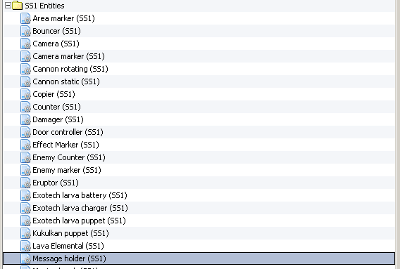
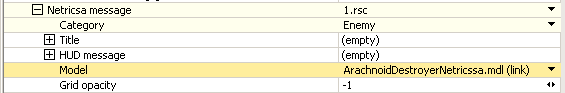
It should be either in selection or a bit deeper
TIPPLE 20 Jun @ 7:50pm 
I have a question. Hi.
How to change blood on enemy from red to green?
dergalaktischekaiser 25 Jun, 2024 @ 7:57am 
hello there, firstly, my serious thanks for this extremely helpful guide.. yet i still must overcome a major troubleshooting issue: after following all your steps in Tier 5, i always get a weird pink texture with a warning that i have a "non-compressed mask texture for my MultiLayer shader"... Every time i type "Y-plane" into the 2nd layer, my entire terrain gets pink with no chance of getting a normal texture from the layers onto it. The screenshot of my issue is here [drive.google.com]. I would appreciate any help.
Alfeos 3 Nov, 2022 @ 1:30am 
Delicious:steamthumbsup:
Umabomber 16 Oct, 2022 @ 3:35am 
This is THE best guide for a beginner, practically everything you need for a good map is taught here. Massive props to everyone who worked on this!
Thanadrax  [author] 16 Oct, 2022 @ 2:51am 
UPD: You can also open the pics with middle mouse button.
Thanadrax  [author] 16 Oct, 2022 @ 2:44am 
IN CASE YOU SEE "INVALID LINK" message on opening image - upon seeing it, just click on the link appearing above, it works. Something wrong with steam
ArtEM-41 16 Oct, 2022 @ 2:31am 
😎😎😎:steamthumbsup: