Barotrauma

Barotrauma

647 ratings
QoL Wiring Tutorial
By Qwerty_XVIII
In this guide, I will describe how to set up some QoL wiring reaching across the board from auto reactor to weapon switch and many more.
I will describe what it's good for, what it does, and what you will need to build it. They're not in a specific order, but are all self-contained.
It's all WIP since I change things as soon I fiddled out a better way or think of new things to implement, it also takes way longer than I thought.
If you have ideas to implement or tips for improvement I would be glad if you share them with me and the community.
33
27
9
3
2
6
6
5
2
   
Award
Favorite
Favorited
Unfavorite
Foreword
A quick note before you go ahead. For this guide you do not need any experience in wiring or logic stuff at all since I tried to explain it as detailed as possible and make every build self-contained. Everything can be build during the campaign and doesn't require the editor to work. It should mostly be possible to follow by looking at the pictures, but every step is written down and numbered too to not miss anything. If you see a 2.0 version of a build, I recommend using this, since it uses often fewer components or is a major optimization. I like to keep the old ones to remind me of the progression I made while experimenting with this wiring aspect of the game, as I started from zero.
However, if something is not clear, don't hesitate to ask since most problems can be solved.

Since the guide got quite long, I decided to separate it in categories to reduce the searching time and make it overall clearer. Below is a list and explanation of what can be found where, with a link directly to the corresponding section.

Power - Here you find everything associated to power like auto reactor builds and batteries as well as power saving ideas

Mechanisms - Here are things like the ballast flora disposal or automated fix foam system

Water and Doors - Extra ballast tanks, a drain or automated hatches are found here

Information and Miscellaneous - Here are things like the low fuel alarm or an airlock display, as well as random stuff like the clock


Power
Basic Reactor Control
A basic reactor control to overwrite the vanilla auto control. It is neither efficient nor pretty, but still better than nothing or a bot.

What you need:
2x Memory
1x Greater
1x Division
6x Wire


How it works:
The load is divided by the maximal output of the reactor and thus the turbine output is calculated. For the fission, the Greater Component just checks if the temperature is at a certain level and pulses the fission on and off until it's around the right temperature.


How to set up:
1) Place all the components, preferably next to the reactor.


2) Connect the SIGNAL_IN_1 Input of the Division Component to the LOAD_VALUE_OUT output of the reactor.
Connect the SIGNAL_IN_2 Input of the Division Component to the Memory Component we use to set the reactor's maximum output SIGNAL_OUT output.
Connect the SIGNAL_OUT output of the Division Component to the SET_TURBINEOUTPUT input of the reactor.


3) Configure the previous mentioned Memory Component to the maximum output of your reactor divided by 100, so we directly get the output value as a percentage, so we can directly send it to the reactor as turbine output.
The max reactor output can be looked up in the editor or simply by connecting a memory component set to 10 to the turbine output and see how much it can output, since upgrades also change the value.


4) Configure the Greater Component to an output of 100 and a false output of 0.
Connect the SIGNAL_IN_1 Input of the Greater Component to the other Memory Component's SIGNAL_OUT output.
Connect the SIGNAL_IN_2 Input of the Greater Component to the TEMPERATURE_OUT output of the reactor.
Connect the SIGNAL_OUT output of the Greater Component to the SET_FISSIONRATE input of the reactor.


5) Configure the Memory Component to 5000. This is our target temperature.


Your reactor should look like this, and this basic control is finished. It should work without problems for at least 2 fuel rods. But be careful when adding and changing rods.

Advanced Reactor Control
This will enhance the fission control to support 4 rods of any type. The turbine control stays as it is, but is required as an input for the calculation.

What you need:
3x Memory
2x Divide
1x Multiply
1x Adder
10x Wire


How it works:
Since there is no in game information on how fission calculation works I had to rely on the wiki which says that you get temperature equal the fuel potential * 2 * fission rate (for 1 thorium fuel rod with a potential of 100 we get 200° for every % fission rate) and for every 1% of turbine power 100° is subtracted from that. When fiddling around with this, I was left with the amount of fission needed to fulfill the turbine demands and add half the target temperature for the reactor because otherwise it would be 0 and no power is generated.


How to set up:
1) Place all the components


2) Configure the memory components
Set the value of the memory component which will be connected to the divide component for turbine output (both components on the bottom of picture in 1) to the reactor's max output divided by 100. In this case, 5000/100 > 50.
Then connect it's SIGNAL_OUT output to the SIGNAL_IN_2 input of the divide component.


Set the second memory component to 50 and connect its SIGNAL_OUT output to the SIGNAL_IN_2 input of the multiply component.


Set the third memory component to 2500 and connect its SIGNAL_OUT output to the SIGNAL_IN_2 input of the adder component.


3) Connect the SIGNAL_IN_1 input of the divide component for the turbine control to the reactor's LOAD_VALUE_OUT output. Connect its SIGNAL_OUT output to the reactor's SET_TURBINEOUTPUT input and to the SIGNAL_IN_1 input of the multiply component.
Also set the clamps to min of 0 and a max of 100.


4) Connect the SIGNAL_OUT output of the multiply component to the SIGNAL_IN_1 input of the adder component.
Set the clamps min to 1 and max to 7500.


5) Connect the SIGNAL_OUT output of the adder component to the SIGNAL_IN_1 input of the other divide component, which controls the fission rate (top one in picture in 1).
Set the clamp max to 7500 too.


6) Connect the SIGNAL_IN_2 input of the divide component to the FUEL_OUT output of the reactor. Connect the SIGNAL_OUT to the SET_FISSIONRATE input of the reactor.
Set the clamp max to 100 and min to 1.


7) Your reactor should be able to hold a temperature at 5000° now no matter how much and what type of fuel is used. Except if you only use a uranium rod, which can only provide a fission rate of 80 due to its low fuel potential.
If you want a lower temperature to save some fuel in the beginning, you can change the value in the second memory component, which is set to 2500.

When powering up the reactor with a high load and lots of fuel rods it can be that it overheats shortly due to the fact that the fission only have to climb like 20% to reach the target level while the turbine have to do the full way and thus needs more than three times as much to reach the target level. With at least one reactor upgrade, it should however not catch fire.
Most Efficient Reactor Control
This build works similar to the advanced controller but is more efficient, because the temperature is only as high as it has to be able to provide the needed power.

What you need:
3x Memory
2x Multiply
2x Division
2x Adder
13x Wire


How it works:
Instead of flat adding, 5000° to be in the optimal temperature range, the needed temperature is calculated and used.


How to set up:
1) Place all components. Turn the reactor off during wiring or do it wile the ship is docked.


2) Configure and connect the 3 Memory Components, beginning with the left one.
Set the first to the max reactor output, divided by 100. Connect its SIGNAL_OUT output to the SIGNAL_IN_2 input of the first divide component directly above it.


Set the second to 50 and connect its SIGNAL_OUT output to the SIGNAL_IN_2 input of the first multiply component.


Set the third to 100 and connect its SIGNAL_OUT output to the SIGNAL_IN_2 input of the second multiply component.


3) Connect the SIGNAL_OUT output of the first division component to both SIGNAL_IN_1 inputs of the multiply components and the SET_FISSIONRATE input of the reactor.
Connect the SIGNAL_IN_1 input of the first division component to the LOAD_VALUE_OUT output of the reactor.


4) Connect the SIGNAL_OUT output of the first multiply component to the SIGNAL_IN_1 input of the first adder component next to it.


Connect the SIGNAL_OUT output of the second multiply component to the SIGNAL_IN_2 input of the first adder component.


5) Connect the SIGNAL_OUT output of the first adder component to the SIGNAL_IN_1 input of the second divide component.


Connect the SIGNAL_IN_1 and SIGNAL_IN_2 input of the second adder component to the FUEL_OUT output of the reactor.
Connect its SIGNAL_OUT output to the SIGNAL_IN_2 input of the second divide component.


6) Connect the SIGNAL_OUT output of the second division component to the reactor's SET_FISSIONRATE input. Set the max clamp to 100 and the min clamp to 0.


The reactor should look like this now and should provide only enough temperature to fulfil the power needs.

Most Efficient Reactor 2.0
After a good night of sleep and thinking of basic math, I saw an easier way to build the efficient controller with fewer components.

What you need:
2x Memory
2x Divide
1x Multiply
8x Wire


How it works:
It works the same as the original most efficient one, but in this build the numbers are shortened, saving almost half the components.


How to set up:
1) Place all the components.


2) Configure the first memory component to the reactors max output divided by 100. In this case, 52 (Camels default max output 5200kW). Connect its SIGNAL_OUT output to the SIGNAL_IN_2 input of the first divide component.


3) Connect the SIGNAL_IN_1 input of the first divide component to the LOAD_VALUE_OUT output of the reactor and connect the SIGNAL_OUT output of the first divide component to the SET_TURBINEOUTPUT input of the reactor and the SIGNAL_ IN_1 input of the multiply component.
Configure its max clamp to 100 and min to 0.


4) Configure the second memory component to 75 and connect its SIGNAL_OUT output to the SIGNAL_IN_2 input of the multiply component.


5) Connect the SIGNAL_OUT output of the multiply component to the SIGNAL_IN_1 input of the second divide component.


6) Connect the SIGNAL_IN_2 input of the second divide component to the reactors FUEL_OUT output, and connect the SIGNAL_OUT output to the SET_FISSIONRATE input of the reactor.


The reactor should look like this and the build is finished.
Fastest Reactor Control (fission based)
With this build the reactor is only be controlled by the fission rate while the turbine is always at 100%.
The temperature will always be at the lowest possible rate, making it resistant to meltdowns. Works better the more fuel is inside i.e. 4 fulgurium rods, which will result in faster reaction to power demand and overvoltage. Let's start!

What you need:
3x Memory
1x Multiply
2x Divide
1x Adder
9x Wire


How it works:
Because the only thing that needs to be moved is the fission rate, which only has to move for about 10% while the reactor is fully loaded, the reaction is that fast. Besides that, math.


How to set up:
1) Place all components. Turn the reactor off during wiring or do it wile the ship is docked.


2) Configure and connect the 3 Memory Components, beginning with the left one.
Set the first to the max reactor output, divided by 100. Connect its SIGNAL_OUT output to the SIGNAL_IN_2 input of the first divide component directly underneath it.


Set the second to 25 and connect its SIGNAL_OUT output to the SIGNAL_IN_2 input of the multiply component.


Set the third to 5000 and connect its SIGNAL_OUT output to the SIGNAL_IN_1 input of the adder component.


3) Connect the SIGNAL_OUT output of the first divide component to the SIGNAL_IN_1 input of the multiply component next to it.
Connect the SIGNAL_IN_1 input of the first divide component to the LOAD_VALUE_OUT output of the reactor.


4) Connect the SIGNAL_OUT output of the multiply component to the SIGNAL_IN_2 input of the adder component.


5) Connect the SIGNAL_OUT output of the adder component to the SIGNAL_IN_1 input of the second divide component. Set its max clamp to 7500 and the minimum to 0.


6) Connect the SIGNAL_OUT output of the second divide component to the reactor's SET_FISSIONRATE input. Connect the SIGNAL_IN_2 input to the FUEL_OUT output ot the reactor.
Set the max clamp to 100 and the min clamp to 0.


7) Now insert your fuel inside the reactor, turn the reactor on and the automatic control off. Turn the turbine to 100%.
Your reactor should look like this and the build is complete.


The only downside I noticed so far is that there is a short and little spike in load when adding fuel rods while the reactor is on and of course that the reactor will burn when the turbine is not at 100%- but this can of course be bypassed with a memory component set to 100 (or more) and connected to the turbine output.

Here are two examples how the reaction is compared to the vanilla auto control


Note that the second dip in load in the second picture is where all the junctions broke and start to burn.
The Math Behind The Controllers
I shortly mentioned how this works, but I decided to give it an extra section to go by it step by step, for those who are interested. Going through all of this again, I even saw a better way to build stuff, so it was at least worth for me to do this.
Some things are from the official Wiki, but most things I figured out while testing in the editor or in game, because in my opinion, it is not that clearly explained in the wiki how things work, and where numbers for calculations came from.


Some preamble before we start:
- The turbine and fission rate can have a value between 0 and 100. Anyting above or below these values has no effect.
- You should always set the max clamp of the division component calculating the turbine output to 100, because it is surely possible that the load given is higher than the max output of the reactor. This would result in a higher fission rate (because the turbine is needed to calculate the fission), which can cause a fire or a meltdown, if it holds for too long.
- When implementing a reactor control, you have to turn off the in game auto controller. The in game thing will be overwritten by the signals from the circuit, but this it is not as stable or precise as the circuit itself and can cause some fluctuations.
- It is mostly a good idea to turn off the reactor completely while building and connecting the circuit, and do this while the ship is docked. Everything stays operational while docked, and you can always can do an emergency shutdown if you notice an unwanted behavior.
- Speaking of unwanted behaviors, often the problem is a wrong number in any of the memory components.
- If your power output is too small but kind of stable, check if there are upgrades applied to the ship, or if the engineer has the reactor perk. You have to adjust the reactor's max output value then.


Since the turbine calculation is the easier one of both, I begin with this one.

1T) To determine the right amount of turbine output, we first need to know of how much power the reactor is capable of generating. To shorten the process, here's a list from the wiki from every vanilla ship without any upgrades and talents.
So for the Dugon, we get a maximum output of, 3000kw with 100% turbine output and 30kw for every 1% turbine output.


2T) To get the turbine output, we need of course the current load of the system. Let's stay with the Dugong and assume we have a load of 1843kw. We now have to divide the load by the maximum output - that would be 1843/3000=0.61433.

3T) But this is not quite the input we need, else the turbine would be below 1%. To get the right input, we have to multiply this by 100, which would result in 61.433 which we can send to the turbine.
However, instead of multiplying by 100 we can also divide the max output by 100, resulting in the same outcome and also saving the components to multiply in the first place. 1843/30=61.433

4T) This is what is used in every reactor build and never really changes. We can verify if we calculated correctly by going reverse - 0.61433*3000=1842.99. This is not exactly what we need, but the game is not that exact with decimal places, too.


So much for the turbine part, let's come to the fission calculation.
To calulate the fission, we first need to understand how fission, turbine output, temperature and fuel potential are working together.

Fuel potential and fission: The fuel potential value detemines how much heat a fuelrod can generate. Uranium has 80, Thorium has 100 and both Fulgurium have 150. But what does these values mean?
For every 1% of fission rate the fuel potential is multiplied by 2 and generates this amount of heat. For example: a reactor with a single thorium fuelrod inside and set to a fission rate of 1% (via a memory component) and a turbine output of 0, creates 200° of temperature. You can see this if you monitor the temperature output with a text display. It also seems to determine the max fission rate, since a single uranium fuel rod can only be set to a fission of 80%.
The fuel potential is added together for every fuel rod that is inside the reactor. With 4 thorium rods the temperature is 800° when 1% fission is set.

Temperature: This is needed to generate the power. If it only would be that easy..
The temperature in the reactor can be between 0° and, 10000°. The optimal temperature is considered, 5000°. This is, however, only the temperature that is needed to produce the full amount of power at 100% turbine output. Tests shown that the needed temperature is equal to the turbine output. 50° per 1% to be exact. For example, to generate 10% of power the temperature in the reactor must be 500° - pretty cool huh.

Turbine output: We already know how to calculate it, but how does it work together with the other variables?
The turbine generates power by consuming heat. The amount of heat consumed is linear and always 100° per 1% of turbine output. So, at 100% the turbine consumes, 10000° of heat to generate the power.

So the conclusion is, we need to generate, 10000° to produce the full amount of power possible - Not!

But why is that so? When generating the 10k°, the turbine would consume all of it, leaving the reactor at 0°. But we know we need a temperature of 5k° to produce the full 100%. So we have to add this, too.


Knowing this, we now can really think of how to calculate the fission rate.

1F) First, the temperature needed to produce the needed power is calculated. To do this, the current turbine output has to be multiplied by 100 (because we remember every 1% uses 100°) and by 50 (because we need 50° for every 1% to heat the reactor to its proper temperature). This can be summed up to turbine output*150 because x*50+x*100=x*150.

2F) Now that we know how much temperature is needed, we can consider the fuel potential. Let's look at our example from 2T), having a turbine output of 61,433. If we multiply it by 150 we get 9214.95 which is the temperature we need.

3F) We now know that we get the double amount of temperature for every 1% fission rate per fuel potential. So we have to divide the needed temperature by the fuel potential multiplied by 2. Good thing the reactor has a fuel_out output. Let's assume we only have one uranium rod inside the reactor (fuel potential of 80)

4F) This leaves us with 9214.95/(80*2)=57.593, which is our fission rate we can send to the reactor.

5F) We are practically done now, but while doing a little recap, another optimization can be found.
Let's see the formula again: > turbine output*150/(fuel potential*2) < This can just be divided by 2 leaving us with turbine output*75/fuel potential. Calculate again with the numbers from the example: 61.433*75/80=57.593
It's the same - noice!


Overcharging The Ship
Since the Hoist the Sails update "overvoltage makes devices perform better". We make use of this and see how much we can squeeze out of these devices.


What you need:
1x Multiply
1x Divide
2x Memory
5x Wire


How it works:
The load simply gets multiplied by a certain amount to rise overvoltage. Mostly, the threshold before the junctions take damage is 70% above the load. With each junction upgrade you get another 10% extra, so it rises to 77%, 84% and 91% after the last upgrade.
Below is a table with ships that differ from those 70%, so you can adjust the components quickly without the need to look in the editor or see when stuff starts to burn.

Ship
Overload threshold
Barsuk
100%
Camel
100%
Herja
100%
Humpback
80%
Orca 2
100%
Typhon
50%
Winterhalter
100%


How to set up:
1) Place all the components, preferably next to the reactor.


2) Connect the SIGNAL_IN_1 Input of the Division Component to the LOAD_VALUE_OUT output of the reactor.
Connect the SIGNAL_IN_2 Input of the Division Component to the Memory Component we use to set the reactor's maximum output SIGNAL_OUT output.
Connect the SIGNAL_OUT output of the Division Component to the SIGNAL_IN_1 input of the Multiply Component.


3) Configure the previous mentioned Memory Component to the maximum output of your reactor divided by 100, so we directly get the output value as a percentage.
The max reactor output can be looked up in the editor or simply by connecting a memory component set to 10 to the turbine output and see how much it can output, since upgrades also change the value. In this example, the max output is 5000.


4) Configure the other Memory Component to 1.65. It is important to use the dot (.) and not the comma (,)
Connect the SIGNAL_OUT output to the SIGNAL_IN_2 input of the Multiply Component.


5) Connect the SIGNAL_OUT output of the multiply Component to the SET_TURBINEOUTPUT input of the reactor.


The build is now finished and your loadout at the maximum as far as the reactor can handle it. As long as no sudden changes in load drop, the junctions will not be damaged.

But what is it good for?
I tested it on the Remora without the auxiliary engine. With normal configuration, I reached a velocity of 20 km/h. With a loadout of 165% I get to 26 km/h. To be fair it took a minute to get there, but it is still an increase of 30%, and it only took a few components and a little more fuel.
With upgrades of the junctions, this can be increased even more.
Overcharge With Reactor Controller
If you want to overcharge the ship but already have an existing reactor controller, I show you how to merge them together. For demonstration, we use the most efficient 2.0 controller, but the build works with every controller you can find here. For a more convenient functionality, it can be toggled with a switch.

What you need:
1x Switch
1x Signal check
1x Multiply
3x Wire


How it works:
The signal check will determine if the switch is on or off. If the switch is turned on, the signal check will output the multiplicator we want to use. This then gets multiplied with the load from the reactor and send to the reactor as an input. Since this replaces the normal input, it can be placed before every controller without altering the reactor controller itself, besides disconnecting the old reactor load input and connecting the new one from the overcharge circuit.


How to set up:
1) Place the new components next to the existing reactor controller for easier connection. The switch mostly goes to command. For a smooth change, better do this while docked and turn the reactor off in the meanwhile.


2) Connect the Signal_Out output of the switch to the Signal input of the signal check component.


3) Configure the signal Check component to an output of 1.5 (this is the multiplicator and can be set up to a max of 1.69, 1.83 or 1.9 depending on the upgrade of the junctions) and a false output of 1. Connect its Signal_Out output to the Signal_In_1 input of the multiply component.


4) At the reactor, disconnect the Load_Value_Out wire to the divide component. Then connect the Load_Value_Out output to the Signal_In_2 input of the multiply component.


5) Set the max output of the multiply component to the reactor's max output, 5000 in this example and the min to 0. Connect its Signal_Out output to the, now free, Signal_In_1 input of the divide component from the reactor controller.


The build is now finished, and the reactor can be turned on again. Start with a turned off switch and check if the power rises when turning it on. Be sure that the junctions don't get damaged while it's activated, if so, the multiplicator is set to high.


As an idea, the switch can also be replaced with another signal to be automatically activated if needed. I like to build it so, that is turned off whenever the engine is on less than 30% power, so less energy is wasted while the ship is parked.
Automatic Battery Switch
Whenever the captain decides to go full speed after parking, the reactor mostly can't catch up in time. An automatic battery switch could help with that. It also bypasses a blackout due to empty fuel rods if you missed the alarm.

What you need:
1x Subtract
1x Memory
1x Greater
1x Relay for every battery used
7x Wire


Optionally 2x Wi-Fi Components, which I had to use because the batteries on the Remora are on the shuttle and wires can't be dragged across the docking port. When the batteries are directly on the ship, regular wires can be used to safe some material.

How it works:
The Subtract Component subtract power output from the reactor by the given load, the Greater Component then checks if the difference is higher than the set value from the Memory Component and activates the batteries by toggling their state to active whenever needed. In this example, the batteries are toggled when the load is 1000kw higher than the power output.


How to set up:
1) Place all components, preferably near the reactor.

2) Connect the LOAD_VALUE_OUT from the reactor to the SIGNAL_IN_1 input of the Subtract Component, connect the POWER_VALUE_OUT to the SIGNAL_IN_2 of the Subtract Component.


3) Connect the SIGNAL_OUT output from the Subract Component to SIGNAL_IN_1 input of the Greater Component.


4) Set the value of the Memory Component to 1000 and connect it to the SIGNAL_IN_2 of the Greater Component.


5) Set the False output of the Greater Component to 0. Connect the SIGNAL_OUT output of the Greater Component to the SET_STATE input of the Relay.

5.1 Optionally connect the SIGNAL_OUT output of the Greater Component to the SIGNAL_IN input of the Wi-Fi Component, set the Channel value to a number that is currently not in use.


5.2 Set the channel of the other Wi-Fi Component to the same value and connect the SIGNAL_OUT output to the SET_STATE input of the Relay.


6) In order to work properly, the power output of the batteries now have to be disconnected from the junction boxes. Instead, the power output must go into a relay. According to the Wiki a relay can throughput 1kw of power and a battery can output 1kw of power, so we need one relay for each battery used to get max throughput. Then connect the power output of the relay to a junction box.

Now you're done. If set up correctly, the batteries will provide power when the reactor can't catch up.
Charge Based Battery Loading
This setup is to save some energy during your voyage and load the batteries based on the current load percentage, and also enables automatic loading while docked to a station.


What you need:
3x Memory
3x Greater
3+1 Relays or one extra for every battery if you have enough free ports on your junction boxes
2x Wi-Fi Component (optional unless your batteries are on a shuttle)
3x XOR
1x And
1x Signal Check
1x Not
a lot of Wires


How it works:
The Memory Components decide when the batteries load with which amount. In this build I use the same components to set the load and the threshold, but it can be separated, to customize it to your needs. Note that the values for charging can only be set in steps of 10. For me, it was sufficient to charge with 50% when going under 10%, 30% from 10 to 30 and 10% above 30 until the batteries are half full at 50%. After that, they will not be charged. When the ship is docked, it will charge with 100% to full capacity because it's free there. The signal for this will come from the docking port. This can only be hooked up while the ship is not docked.
To simplify things a bit, I rebuild this setup and set up two displays, the upper shows the charge in % and the lower shows the current battery charge in %. The lever indicates the airlock. Note that the battery will load with full 100% when docked, independent of the current load %.


How to set up:
1) Place the components, preferably next to batteries because it will save you a bit of running around when connecting stuff to them.

2) Memory Components
Configure the Memory Components. Set one to 50, one to 30 and one to 10. Place a fourth one a bit aside and configure it to 100. This one is for later when the override with the docking port comes.

Connect the SIGNAL_OUT output of the Memory Component, which is set to 50 to the SIGNAL_IN_1 input of the first Greater Component (let's refer to it as Gr 50). Also connect it to the SIGNAL_IN_1 input of a relay (we call that Re 50)


Connect the SIGNAL_OUT output of the Memory Component, which is set to 30 to the SIGNAL_IN_1 input of the second Greater Component (let's refer to it as Gr 30). Also connect it to the SIGNAL_IN_1 input of another relay (we call that Re 30).


Connect the SIGNAL_OUT output of the Memory Component, which is set to 10 to the SIGNAL_IN_1 input of the third Greater Component (let's refer to it as Gr 10).


3) Greater Components
Configure the Greater Components, so all have an Output of 1 and a False Output of 0. Then connect the CHARGE_% of one Battery to each of the Greater components SIGNAL_IN_2 input. All Batteries should have the same load anyway.


Now connect the SIGNAL_OUT output of the Greater Component Gr 50 to the first XOR Component (let's call that X 10).


Connect the SIGNAL_OUT output of the Greater Component Gr 30 to the XOR X 10 and the second XOR Component (X 30) as well as the And Component. Which input you choose doesn't matter.


Connect the SIGNAL_OUT output of the Greater Component Gr 30 to the free input of the XOR X 30 and the And Component.


4) XOR
Connect the X 10 SIGNAL_OUT output to the Signal Check Component SIGNAL_IN and connect a second wire to the third XOR Components SIGNAL_IN_1 input which has no inputs at the moment (refer to it as X 10 2)


Connect the X 30 SIGNAL_OUT output to the Relay Re 30 SET_STATE input.


Connect the X 10 2 SIGNAL_OUT output to the Relay Re 10 SET_STATE input. Now Connect the SIGNAL_IN_2 Input of X 10 2 to the SIGNAL_OUT output of the Not Component.


5) And, Not
Connect the SIGNAL_OUT output of the And Component to the Relay Re 50 SET_STATE input. Make sure the Output is set to 1 and the False output is set to 0.


Connect the Not components SIGNAL_IN input to the SIGNAL_OUT output of the Signal Check Component.


6) Signal Check
Configure this component to Output 10 and False Output 0. The Target signal should be 1.
Connect another wire from the SIGNAL_OUT output to the SIGNAL_IN_1 input of Relay Re 10.


7) Relay
Connect the Relay Re 50 SIGNAL_OUT_1 to each battery's SET_CHARGE_RATE_%.


Connect the Relay Re 30 SIGNAL_OUT_1 to each battery's SET_CHARGE_RATE_%.


Connect the Relay Re 10 SIGNAL_OUT_1 to each battery's SET_CHARGE_RATE_%.


The main build is now complete. But if you want the automatic load while docked, continue with the next step.


8) Docking Override
Connect the Memory Component's Mem 100 SIGNAL_OUT we set up in the beginning to the Relay Re 100 SIGNAL_IN_1 input.


Connect the Relay Re 100 SIGNAL_OUT_1 to each battery's SET_CHARGE_RATE_%. Also connect the SET_STATE input to the docking port STATE_OUT output. Note this is only possible while the ship is not docked and don't forget your diving suit.

Charged Based Battery Loading 2.0
Since the initial build uses a lot of inputs we maybe need for later projects, I managed to figure out a way that is not even faster to build, but also uses fewer components or inputs.

What you need:
1x Relay
1x Multiply
1x Add
1x Greater
1x Cos
3x Memory
10x Wire

Note that 1x Memory and 1x Add are optional, but handy to configure the charging rate in the end to your needs. That's why I use them in this build.


How it works:
All I remember of trigonometry is that the cosine of 0 is 1 and the cos of 1 is 0. If we multiply this by 100 we have our charging inputs. Note that with this configuration alone, the charge rate of the batteries will not be overwritten when the target level of 50 (through third mem) is reached and the greater component deactivates the relay. However, if you configure the Add component to 39 it reaches a charging rate of 0 when hitting 49, making it irrelevant to set up a second overwrite circuit.


How to set up:
1) Place all the components close to the batteries


2) Configure the Memory Components. The first one to 38. Connect its SIGNAL_OUT output to the SIGNAL_IN_1 input of the Add Component.


The second one to 100. Connect its SIGNAL_OUT output to the SIGNAL_IN_2 input of the multiply Component.


The third one to 50. Connect its SIGNAL_OUT output to the SIGNAL_IN_1 input of the Greater Component.


3) Connect the battery's CHARGE_% output to the SIGNAL_IN_2 input of the Add Component. Connect the SIGNAL_OUT output of the Add Component to the SIGNAL_IN input of the COS Component.


4) Connect the SIGNAL_OUT output of the COS Component to the SIGNAL_IN_1 input of the Multiply Component.


5) Connect the SIGNAL_IN_2 input of the Multiply Component to the SIGNAL_OUT output of the second Memory Component, we set to 100. Connect the SIGNAL_OUT output of the Memory Component to the SIGNAL_IN_1 input of the Relay Component.


6) Configure the Greater Components Output to 1 and False output to 0. Connect the battery's CHARGE_% output to the SIGNAL_IN_2 input of the Greater Component. Then connect the SIGNAL_OUT output of the third Memory Component, we set to 50, to the SIGNAL_IN_1 input of the Greater Component. Connect the SIGNAL_OUT output to the SET_STATE input of the Relay Component.


7) Connect the SIGNAL_OUT_1 output of the Relay Component to the SET_CHARGE_RATE input of each battery.


Your battery should look like this now.
Prevent Hazardous Overvoltage
If your captain likes to do full stops while going full speed, or you like to overcharge the ship to the max, you know how fast the junction boxes can fry to death. With this system, the load spike will mostly be absorbed by the batteries.

What you need:
8x Memory
3x Multiply
3x Greater
3x Not
2x And
1x Subtract
1x Signal Check
1x Divide
A few stacks of Wire


How it works:
Whenever the produced power is more than 1.7 times the load, the junction boxes will take damage (without any upgrades) and eventually start to burn. This build will calculate if the power is above the threshold of 1.7 times the load, and then we have to divide this by the loading capacity of our batteries. As if this wouldn't be enough, this of course only works if the batteries are not full. We also have to keep in mind that the batteries can only be loaded in 10% steps, so there need to be a certain area in between the overvoltage that's harmful and the non-harmful one, and we have to choose a value for when the power output is considered ok again, so the loading of batteries can be stopped.

When everything is wired up correctly, the load curve should look like this:


instead of this:


How to set up:
Place all the components wherever is enough space to do so.


To simplify things, let's chop it up in its 4 functionalities:
- 1 or the green square is the calculation of the overvoltage, when it's too high, low enough and the amount we need to get rid of to save the junctions.
- 2 or light blue square is for tuning it on and off again
- 3 or orange square is the calculation to set the battery load
Everything else is for additional control or fallback


We begin with section 1. - the base calculation, and go from the top right to bottom left row by row. Don't be worried when I'm not mentioning all wires visible on the screenshot. It's mostly easier to go piece by piece and connect the secondary inputs in the end. To avoid things to get mixed up, the arrangement of the components shown is like following, where M1-6 are the memory and X1-3 are the multiply components:
M4 X1 M1
M5 X2 M2
M6 X3 M3

1) Configure the first memory component (M1) to 1.55 and connect its SIGNAL_OUT output to the SIGNAL_IN_2 input of the first multiply component.


2) Connect the first multiply components SIGNAL_IN_1 input to the LOAD_VALUE_OUT output of the reactor.
Connect its SIGNAL_OUT output to SIGNAL_IN input of the memory component left to it (M4).


3) Connect the SIGNAL_OUT output of the memory component (M4) to the SIGNAL_IN_2 input of the subtract component.


4) Configure the second memory component (M2) to 1.7 and connect its SIGNAL_OUT output to the SIGNAL_IN_2 input of the second multiply component.


5) Configure the clamp max of the second multiply component to the max output of the reactor, and connect its SIGNAL_IN_1 input to the LOAD_VALUE_OUT output of the reactor.
Connect its SIGNAL_OUT output to SIGNAL_IN input of the memory component left to it (M5).


6) Connect the SIGNAL_OUT output of the memory component (M5) to the SIGNAL_IN_2 input of the greater component (G2) left to it in the same row.


7) Configure the third memory component (M3) to 1.4 and connect its SIGNAL_OUT output to the SIGNAL_IN_2 input of the third multiply component.


8) Configure the clamp max of the third multiply component to the max output of the reactor, and connect its SIGNAL_IN_1 input to the LOAD_VALUE_OUT output of the reactor.
Connect its SIGNAL_OUT output to SIGNAL_IN input of the memory component left to it (M6) and to the SIGNAL_IN_1 input of the first greater component (G1) in the top row.


9) Connect the SIGNAL_OUT output of the memory component (M6) to the SIGNAL_IN_1 input of the greater component (G3) left to it in the same row.


Now for the second part - turn it on and off again

10) Configure the first greater component (G1) to an output of 1 and a false output of 0.
Connect its SIGNAL_IN_2 input to the POWER_VALUE_OUT output of the reactor. Connect its SIGNAL_OUT to the LOCK_STATE input of M5.


11) Configure the second greater component (G2) to an output of 1 and a false output of 0.
Connect its SIGNAL_IN_1 input to the POWER_VALUE_OUT output of the reactor. Connect its SIGNAL_OUT output to the SIGNAL_IN_1 input of the first and component and the SIGNAL_IN input of the first not component, both in the same row left of it.


12) Configure the third greater component (G3) to an output of 1 and a false output of 0.
Connect its SIGNAL_IN_2 input to the POWER_VALUE_OUT output of the reactor. Connect its SIGNAL_OUT output to the SIGNAL_IN_2 input of the second and component and the SIGNAL_IN input of the second not component, both in the same row left of it.


13) Configure the first and component to an output of 1 and a blank false output.
Connect its SIGNAL_OUT output to the SIGNAL_IN input of the memory component next to the signal check (M7).


14) Configure the second and component to an output of 0 and a blank false output.
Connect its SIGNAL_OUT output to the SIGNAL_IN input of the memory component next to the signal check (M7).


15) Connect the SIGNAL_OUT output of the first not component (N1) to the SIGNAL_IN_1 input of the second and component.


16) Connect the SIGNAL_OUT output of the second not component (N2) to the SIGNAL_IN_2 input of the first and component.

If you take a look at the set-up, you will notice that the connections cross from the not to the and components. This intended and should look the same in your set-up if you choose to place the components the same way.

The last part from this how to is in the second part of this guide, since I ran out of characters in this one.
Prevent Hazardious Overvoltage part 2
Since I ran out of characters in the first part (now I know that's even possible) I continue to describe how to set up this in this section.

Part 3, simple calculation and the other components.

17) Connect the SIGNAL_IN_1 input of the subtract component to the POWER_VALUE_OUT output of the reactor. Connect its SIGNAL_OUT output to the SIGNAL_IN_1 input of the divide component.


18) Configure the last memory component (M8) to the combined loading power of all batteries included and divide that by 100. In this example both batteries of the Dugong can load up to 800kw making it 1600 in total leaving 16 when divided.
Connect its SIGNAL_OUT output to the SIGNAL_IN _2 input of the divide component.


19) Configure the min clamp of the divide component to 0 and connect its SIGNAL_OUT output to the SET_OUTPUT input of the signal check component.


20) Connect M7 to the SIGNAL_IN input of the signal check component and to the SIGNAL_IN input of the third not component (N3)


21) Configure the signal check component to a false output of 0 and a target signal of 1. The output is set by the divide component.
Now connect the SIGNAL_OUT output to the SET_CHARGE_RATE Input of all the used batteries.


22) Now connect the not components (N3) SIGNAL_OUT output to the LOCK_STATE inputs of M4, M5 and M6.


Congrats! You made it to the end and have hopefully a working overvoltage prevention mechanism.
However, a little bug in the system is still there- if the system goes on, it can happen that the circuit does not get disrupted when the power increases again. This will cause the battery load to increase to 100%. This can be stopped by letting the power go down to below the point where it wasn't harmful when the overvoltage happened in the first place.
Prevent Oxygen Overload (or how to save fuel)
The O² generator normally produces enough oxygen for 5-6 people per room per second. Because no one have that many people on board and the O² generator normally is one of the most power hungry devices on the ship, this can safely be limited and also save a vast amount of power, especially in the early stages of the game.

What you need:
1x Memory
1x Relay
5x Greater
5x Oxygen Detector
4x Or
19x Wire


How it works:
The Oxygen Detectors read the current O² level. If it drops below the value we set in the Memory Component, the Relay will turn on and let power through to the oxygen generator until the O² level is above the set value. Normally the O² level raises by 10-30% when it just starts for a few seconds depending on the used ship and configured generator. Feel free to experiment with the numbers which fits best for you. Keep in mind that a low oxygen warning pops up when it's below 45ish.
Optionally, you can connect the Oxygen Detectors to your status terminal to monitor the O² level if it is not available already.
Unfortunately, the input of the SET_STATE of the relay only detects one input, so we need to install a workaround with Or Components. We need one less Or Component for every Greater Component we use (4 or for 5 greater, 2 or for 3 greater, etc.).


How to set up:
1) Place the Oxygen Detectors in crucial rooms like command, med bay or engineering. Or rooms where people often stay. Place the other components next to the oxygen generator. One Greater Component for every used Oxygen Detector and one less Or Component.

2) Set the Memory Component to a value that fits your needs. Anything between 50 and 80 should be sufficient. Connect the SIGNAL_OUT of the Memory Component to the SIGNAL_IN_1 input of all used Greater Components


3) Connect each SIGNAL_OUT output of every Oxygen Detector to the SIGNAL_IN_2 input of each Greater Component.


4) Set the False output of all Greater- and Or Components to 0.


5) Now connect the Greater Components SIGNAL_OUT output to the Or Components. Each two greater to one Or Component, use SIGNAL_IN_1 and SIGNAL_IN_2.


Then connect the SIGNAL_OUT output of Or Components which have both inputs occupied to a third Or Component. Repeat until you have only one signal going out. To visualize what I mean, I made a screenshot:


6) If you have an uneven number of greater Components, there will be one Or Component which only one input. Connect the single output I mentioned in point 5) to the second input of this component. The last remaining SIGNAL_OUT output of the Or Component goes into the SET_STATE input of the Relay.


7) Connect a power source to the POWER_IN input of the Relay and connect the POWER_OUT to the Oxygen Generator. You can use a Junction Box or a Battery- I prefer batteries as power source but since the Remora's batteries are on the shuttle this is not an option in this case.
Don't forget to disconnect the original power supply of the Oxygen Generator.


You are now ready with this build. Check the Status Monitor if the build works as intended. For testing, I tend to use a value like 90 in the Memory Component to have more time to troubleshoot before O² runs out if anything went wrong.


Mechanisms
For faster navigation the links to the different sections again:

Power - Here you find everything associated to power like auto reactor builds and batteries as well as power saving ideas

Water and Doors - Extra ballast tanks, a drain or automated hatches are found here

Information and Miscellaneous - Here are things like the low fuel alarm or an airlock display, as well as random stuff like the clock
Automated Fixfoam System
Whenever a big leakage must be sealed quickly, fixfoam grenades are very handy. Even more when their use can be automated with detonators and no one has to be in or around the damaged hull to get in danger or risk getting flushed out and being eaten alive.


What you need:

1x Lever
1x Signal Check +n for every detonator in use - here I use three, so 4 are needed
2x And
1x Or
1x Memory
1x Xor
1x Delay
1x Adder
1x Not
1x Water detector
3x Light component (optional)
22x Wire


How it works:
The system gets activated by pulling the lever in command or wherever it fits your needs the best. After that, the detonators get active when the door to the dedicated room is closed and there's high water pressure for a certain duration. The detonators will cycle to the next position whenever the criteria are met. After all have been activated, the system resets itself, starting anew. You only need to refill the grenades in between, of course. You can extend the number of detonators as you like, but if you have more than three, a relay must be built in between the adder and signal checks to split the signal further.


How to set up:

1) Place all the components in the chosen room, usually first in the ballast tanks, while the activation lever goes to the command room.


2) In the water detector, connect the High_Pressure output to the delay's Signal_In input. Set its output to 1 and false output to 0.


3) In the delay component, set the delay duration to a value that you want the room to be fixed after an incident. Here I chose 10. Check the "Reset when different signal received" box. Connect the Signal_Out Output to the Signal_In_1 input of both the or as well as the xor component.


4) Set the or component to an output of 1 and false output of 0. Connect its Signal_Out output to the Signal_In_2 input of the xor component.


5) Set the xor component to an output of 1 and a false output of 0. Connect its Signal_Out output to the Signal_In_2 input of the first and component (left one in picture at 1).


6) Now connect the hatch or door to this room to the not component's Signal_In input, and connect the Signal_Out output of the not component to the Signal_In_1 input of the first and component.


7) Set the first and component to an output of 1 and a false output of 0. Connect the Signal_Out output to the Signal_In_2 input of the second and component right next to it.


8) Set the second and component to an output of 1 and a false output of 0. Connect its Signal_In_1 input to the lever which was placed in command and should activate or deactivate the whole system. Now connect its Signal_Out output to the Signal_In_1 input of the adder component.


9) Set the adders min clamp to 0 and connect its Signal_Out output to all used signal check components Signal_In input and the Signal_In input of the memory component.


10) Set the memory component to 0 and connect its Signal_Out output to the Signal_In_2 input of the adder component.


11) Now for the signal check components - configure the ones who should lead to the detonators (right side on picture in 1)). Set all to an output of 1 and a false output of 0. Set the target signal for the top one to 1, the middle to 3 and the one on the bottom to 5. If you use more, continue in steps of 2 as before. Then connect their Signal_Out output to the top, middle and bottom detonators Signal_In input next to them. One for each. If you use lamps to indicate active detonators, connect them as well to the Set_State input of the lamp.


12) Now configure the last signal check component (left of the adder on picture in 1)) to an output of -6 and clear the false output to make it blank. The target signal shall be 6. Connect its Signal_out output to the Signal_In_1 input of the adder component.


The build is now complete and whenever the system is activated through the lever and the water pressure in this room will be high while the door is closed one fixfoam grenade will trigger automatically and closing all the leaks. Configure the time for that as you wish in the delay component.

Note: The xor circuit is to transfer the constant signal of the water detector to a pulse, if this is not the case, the adder component would constantly add the inputs together and all grenades would trigger together.
The last signal check is for resetting the count to start again with 0 after the last one has been activated. If you use more than three you have to decrease the output to more than -6, or just enter -9999 because the min clamp of the adder is set to 0 anyway.
The target signal goes in steps of two because the pulse from the xor circuit is triggers twice - when being activated and when deactivated. The good thing with this is that the detonators are only armed for a short amount of time and when changing grenades it is less likely to accidentally blow them off while inserting them because the detonator might be active. The downside of this is that you should only activate it before it is triggered, or else it does nothing until the leak is fixed and then sets off the first grenade. If this should happen, you simply can set the memory component manually to 0 and check if the first grenade is loaded.
Ballastflora Disposal Mechanism
This setup is to clear the root of a pest ballstflora with the ease of pulling levers. But be careful there are explosives involved and hull fixing or repairing of pumps can be necessary afterwards.


What you need:
2x Lever
3x Relay
2x Delay
1x Not
1x And
1x Memory
2x Detonator
15x Wire

One Lever and the And Component are optional but erase the potential to accidentally blow up the ballast or crew members inside due to misclicking.


How it works:
The normal inputs from the Navigation Terminal are routed through a relay and can be overwritten by deactivating the relay. This build overwrites the normal input first with the Memory which is set to -100, so the pump will drain all water first since the flora gets only half damage when submerged in water.
After the water is drained (activate the system and estimate the duration until all water has been pumped out) the Delay Component deactivates the power supply, so the flora is not able to pump in water again. A second later the second Delay Component activates the detonators and depending on the used explosive the flora is gone or nearly dead, but be prepared to do repairs immediately.


How to set up:
1) Place all the components. If you use two levers, I recommend placing one in the command and the other above the ballast tank or where it can be reached easily without being close to the detonators.


2) Connect the two Levers SIGNAL_OUT output to the And Components SIGNAL_IN_1 and SIGNAL_IN_2 inputs.

3) Connect the And Components SIGNAL_OUT output to the Not Components SIGNAL_IN input, the Delay Component, which will be connected to the detonators, SIGNAL_IN input and to the Relay Component, which will be connected to the memory, SET_STATE input.


4) Connect the Not Component's SIGNAL_OUT output to the SET_STATE input of the Relay Component which will be connected to the Navigation Terminal and to the SIGNAL_IN input of the Delay Component which will be connected to the relay that transfers the power.


5) Configure the Memory Component to -100 and connect its SIGNAL_OUT output to the SIGNAL_IN_1 input of the relay, which is connected to the And Component.


6) Configure the Delay Component which is connected to the Not Component to a value that is sufficient for the pump to drain all the water. For me, 9 was enough with the big pump in the Humpback. Also enable the "Reset when different signal received" checkbox, so you can disable the process in an emergency (if there's one bigger than alien plants eat your ship at the moment). Then connect the SIGNAL_OUT output to the relay that transfers the power SET_STATE input.


Configure the Delay Component which is connected to the And Component to a value higher than the other one. Connect it's SIGNAL_OUT output to the Detonators ACTIVATE input.


The Detonator should look like this


7) Now disconnect all connections from the pump and connect the power from the Junction Box to the Relay Component, which is connected to the Delay Component POWER_IN input. Proceed to connect the POWER_OUT putout to the pump's POWER_IN input.


Connect the Relay Component which is connected to the Memory Component SIGNAL_OUT_1 output to the SET_TARGETLEVEL input of the pump.


Connect the Navigational Terminal VELOCITY_Y_OUT output to the Relay Component's SIGNAL_IN_1 input which is connected to the Not Component.


8)Your pump should look like this now.


9) It's time to make a cheap test if it works. Place a Light Component and connect the SET_STATE input of it to the Delay Component, which is connected to the Detonators. Now park your ship somewhere directly under a rock, so it will not hit the ceiling with much force. Now activate both levers and take a look what happens. If all is set up correctly the ballast will be drained and shortly after the light will light up. If it turns on before the water is drained, adapt the values in the Delay Components. Now you deactivate the system by pulling the levers again. You can repeat the process and try to interrupt it by pulling a lever before the light turns on- it should stay out then.
Now turn the system off and when the light is off and only then (yes, be sure it's turned off) arm the detonators with whatever explosive you feel like. I recommend grenades though. They do not damage the hull and should have enough force to destroy the flora in one go.
Fire Extinguisher
If you encounter a lot of fires, it is time to think about an automated fire fighting system before your crew is crispy and your oxygen is suddenly depleted.

What you need:
1x Signal check
1x Or
1x Smoke detector
1x Water detector
5x Wire


How it works:
When a fire is detected, the pump will pump in water until no fire is detected anymore. After that it will pump out all water like it would normally do.


How to set up:
1) Place all the components in the room you want to be automatically extinguished.


2) Connect the smoke detector to the SIGNAL_IN input of the Signal check component.


3) If there's a preset water detector in the room, disconnect its SIGNAL_OUT wire to the pump. Then connect the SIGNAL_OUT output to the SIGNAL_IN_2 input of the or component.


4) Connect the SIGNAL_OUT output of the or component to the SET_STATE input of the pump.


5) Connect the SIGNAL_OUT output of the signal check component to the SET_SPEED input of the pump. Configure its target signal to 1, the output to 100 and false output to -100.


Your pump should look like this, and the build is now complete. Optionally, you can disable the doors while a fire occurs as the water doesn't get drained before the fire is out because people or bots keep entering the room for whatever reason.


It is even possible to use pumps in a room below or above the burning room, when working with disabling the doors, ducts or hatches. But I don't take any response when the ship is sinking.
Lazy Fire Extinguisher
Whenever there's a fire and no one feels responsible or the next handheld fire extinguisher is just too far away or, like always when you need it, not in its place, this build is just right for your ship. Just close the door and wait until it is out.


What you need:
1x Relay
1x Not
1x Smoke Detector for every potential fire source
1 less Or Component for every Smoke Detector used
7x Wire


How it works:
As soon as a fire breaks out and is detected, the oxygen generator is turned off until the fire suffocates due to oxygen loss. When the detectors sense no fire, the oxygen generator is turned on again.


How to set up:
1) Place all the Smoke detectors you need. Let's assume three are used - connect the first two to an Or Components SIGNAL_IN_1 and SIGNAL_IN_2 input.


Connect its output to an input of the next Or Component. Now connect the last Smoke Detector's SIGNAL_OUT output to the remaining free input of the Or Component.


Configure all Or Components to Output 1 and False Output 0.

2) Now connect the SIGNAL_OUT output of the last OR Component to the SIGNAL_IN input of the Not Component. Configure the Not Component to an Output of 1 and False output of 0.


Proceed with connecting the SIGNAL_OUT output of the Not Component to the SET_STATE input of the Relay Component.


3) The power of the oxygen generator should be disconnected and routed through the relay so that it is only active when the state of the Relay is active (1) too.


Optional adjustment:
If you use a build to activate the generator only when a certain threshold is reached, this setup has to be adjusted a bit. Instead of the Not Component, a XOR Component is needed.

4) Connect the SIGNAL_OUT output of the last OR Component from the Smoke Detectors to the SIGNAL_IN_2 input of the Not Component. Now connect the SIGNAL_OUT output of the last OR Component from the Oxygen Detectors to the SIGNAL_IN_1 input of the XOR Component.


5) Connect the SIGNAL_OUT of the Not Component to the SET_STATE of the Relay Component that provides power to the oxygen generator.


Silent Mode
Sometimes it's better to just go incognito and try to avoid just another swarm of Hammerheads or the usual squad of Moloch's waiting around the next corner for you. To do so, it is necessary to turn off all things that create noise. While testing, I noticed that only the reactor, the engine and walking/ running players create "visible" noise on the sonar. Other things like the deconstructor, oxygen generator or pumps are not shown.

What you need:
4x Relay
1x Not
1x Divide
1x Memory
1x Signal check
1x Lever
20x Wire


How it works:
We have to ensure that the sub gets as silent as it can be. Most noise comes from the reactor and the engine. The first can easily be turned off. The engine, however, can't just be turned off, else we would drift right into the next wall or the enemies. But tests have shown that the engine does not give off noise when running under 10%. The oxygen generator and the pumps doesn't seem to give off any noise at all, at least it is not shown on the sonar- and even walking people are visible on the sonar.
So we basically have to turn off the reactor or set turbine and fission rate to zero, since we can't turn it on by signals if it's completely shut down. After that, we have to configure the engine to run on 10% of the usual power. Oh, and don't forget to turn off the sonar ;)


How to set up:
1) Place all the components. I would recommend to place one relay near the batteries (R1), one near the junctions (R2) and two next to the engine(R3, R4) as well as the memory and divide component. The lever and not are good together next to the navigation terminal, and the signal check can go next to the reactor. Also dock the ship to a station of your choice because engine, pump and navigation have to be disconnected in the process.

2) Connect the POWER_OUT of all available batteries to the POWER_IN input of the relay you put next to them (R1). Connect the POWER_OUT of this relay to the POWER_IN of the engine, the navigation terminal and the main ballast pump. If you have multiple pumps you probably have to use another relay to power them because one can only provide 1000kw which is barely enough for the 3 devices.
Connect the SET_STATE input to the STATE_OUT output of the lever.


3) Disconnect the POWER_IN input wire of the engine, the navigation terminal and the main ballast pump leading to the junction's POWER input. Then connect a wire from a free POWER port of a junction to the relay we placed near junctions (R2), and one to a relay at the engine (R3). Connect the POWER_OUT output of the relay R1 to the POWER_IN input of the navigation terminal and the main pump. Connect the SET_STATE input of R1 to the STATE_OUT output of the not component.
The POWER_OUT of the relay next to the engine (R3) goes to the engine's POWER_IN input.


4) Next we configure the relay (R3) next to the engine which provides power from the junction.
Connect its SET_STATE input to the not components STATE_OUT output. Connect the SIGNAL_IN_1 to the VELOCITY_X_OUT output of the navigation terminal, and connect the SIGNAL_OUT_1 output to the SET_FORCE input of the engine. Also disconnect the wire from the engine which goes directly into the SET_FORCE input from the navigation terminal.


5) Connect the levers SIGNAL_OUT output to the SIGNAL_IN input of the signal check and the not component, as well as the SET_STATE input of the second relay by the engine (R4).


6) Connect the SIGNAL_OUT output of the signal check to the SET_FISSIONRATE and SET_TURBINEOUTPUT input of the reactor. Configure its Output to 0 and clear the false output.


7) Configure the memory component to an output of 10 and connect its SIGNAL_OUT output to the SIGNAL_IN_2 input of the divide component.


8) Connect the SIGNAL_IN_1 input of the divide component to the VELOCITY_X_OUT output of the navigation terminal. Connect its SIGNAL_OUT output to the SIGNAL_IN_1 input of the second relay by the engine (R4). Set its max clamp to 10 and min to -10.


9) Connect the SIGNAL_OUT_1 output of R4 to the SET_FORCE input of the engine.


The build is now complete. If everything is correctly set up, the reactor should turn silent when the turbine tuns out and the engine should run with 10% force max, making it dead silent. The navigation terminal will be usable as well, while the status monitor and everything else will turn off. Remember to have some diving masks ready if this mode is on for a bit. If no one moves or runs fast, the ship will not emit any sound.
Also, there is a little downside to this - since some engines run on more than a thousand watts, one relay alone can possibly limit its potential overall, even when not in silent mode. One solution is to use a special relay, which can be found in some ships like the Barsuk (next to the battery is a relay capable of transferring 5 kW of power, as far as I know). You can also place more than one relay to provide power to the engine.
Weapon Switch
With this build, it is possible to switch the used ship weapon without the need of running to the next periscope. This comes in handy when the weapons are spread out like in the Remora or your crew is understaffed. I will show you how to use two weapons for each periscope, but it is possible to use more if needed.


What you need:
1x Switch or Lever (it's bigger and easier to hit, but I like the status indicator of the switch more for this build)
2x Relay
1x Not
11x Wire


How it works:
The default connection from the periscope to the weapon will be lead through a relay. A second connection will be established via a second relay, which is only online while the switch is active. To set the correct states, the not component will be set in front of one relay.


How to set up:
1) Place all the components. The switch should be reachable from the periscope. Tests have shows that it is better to place the components a bit away from the switch, so they did not get highlighted while trying to push the switch.


2) Connect the SIGNAL_OUT output from the switch to the SIGNAL_IN input of the Not component and to the SET_STATUS input of the second relay component (the upper one in picture by 1).
Switch

3) Connect the SIGNAL_OUT output of the not component to the SET_STATE input of the first relay Component (bottom one in picture in 1).


4) Connect the POSITION_OUT output of the Periscope to each relay's SIGNAL_IN_1 input, and connect the TRIGGER_OUT output to each SIGNAL_IN_2 input of both relay components.
Periscope

5) Connect the SIGNAL_OUT_1 output of the first (bottom) relay to the POSITION_IN input of the weapon that is controlled by default from the periscope you're working on. Connect the SIGNAL_OUT_2 output to the TRIGGER_IN input of the same weapon.


Then do the same with the second (upper) relay and connect it to the second weapon you want to control.


6) Now you only have to disconnect the original wires from the weapon that is controlled by default by the periscope.

The build is now completed. By default, you should control the original weapon when the switch is turned off and the secondary weapon, then it's turned on without moving a single step.

Water and Doors
For faster navigation the links to the different sections again:

Power - Here you find everything associated to power like auto reactor builds and batteries as well as power saving ideas

Mechanisms - Here are things like the ballast flora disposal or automated fix foam system

Information and Miscellaneous - Here are things like the low fuel alarm or an airlock display, as well as random stuff like the clock
Automatically Shutting Airlock
If your away team tends to forget to close the airlock after leaving the ship, and you don't want to go there every time and close it by hand or press a button, this automatic solution is what you need.

What you need:
1x Motion Sensor
1x Wire


How it works:
The motion sensor is configured that it only outputs a value when no one's around, and so closing the door automatically.

How to set up:
1) Place the motion sensor at the upper end of the airlock door, directly under the hull.


2) Connect the SIGNAL_OUT output of the sensor to the SET_STATE input of the door.
Then configure the sensor to Target: Human. Set the checkmark to Ignore Dead. With this setting, you ensure that no dead monsters floating near your airlock keep the door open. I haven't test it, but it should also keep all husks outside.
Set the Range X to 200 and Range Y to 100. Configure the Detect Offset to X 45 and Y -90. Now set the output to nothing (blank) and the false output to 0.


This was it, basically. Note that these values are for the airlock in the Dugong only.


However, if you're interested in how the motion sensors works or where these numbers come from, read on. This should help to find the right values for your needs because there obviously is no highlighted square around the sensor when you're not in the editor.

By default, the sensor is set to a range of 100 X and Y where every value equals 2 cm in game. For reference, a character is about 1.70 m high, a door around 2.10 m high and a hatch is about 1.30 m wide.
If no offset is chosen the center of the sensor is the center of the detected area where the X range goes to the left and right side while the Y range goes to the top and bottom. So if a range of 100 X and Y is set it detects an area of 1 m left and right aslwell as 1m to the top and bottom of the sensor which looks like this:


The offset values will move the detected area, where negative X values will move the area to the left and positive to the right while positive Y values will move the area to the top and negative to the bottom. The offset also seems to be a 1 to 1 cm ratio and cannot be higher than the detected area.
Knowing this, we could start to estimate how big the needed area is. Since we know the door is 2.1 m and a character is only 1.7 m we can leave the Y value at 100 because it will mostly cover the whole corridor when set to the right offset.
To get the offset for Y we see where the detector is placed- is it directly at the hull? Then set is to -100 is it a bit below the hull set it to -90 or the area will be inside the hull, or worse, in the next room below it where a standing person would prevent the sensor from shutting down (like a security officer standing on a gun).
The X range is a bit more difficult and maybe have to be test several times until it fits your needs. While testing, I estimated a distance about 1 m where the door can be used, so it should be at least set to 100. But this is very short and when the water flows in, and you move by a centimeter the door will shut in front of you which is annoying. So the range gets increased to 200 which result in 2 m left and right of the sensor. Let's measure if it's enough to detect the whole room. How you may ask, I don't have a ruler in game... Well not exactly, but


As said, a character is around 1.7 m standing. with arms out lying on the ground its around 2.1 m. So the offset should be moved around 40-50 cm to fill the room. Let's verify in editor Offset x=45 Y-90:

Pretty OK, I would say.
Custom Airlock From Docking Hatch
Some ships have a docking port at the top and bottom side, but only one usable airlock. With customizing these docking ports, it is possible to have another entrance/ exit and don't have to swim around the whole ship. This time we use a Typhon2 because it has a nice airlock docking port at the bottom which can't be used by default.

What you need:
1x Button
1x Xor
1x Signal check, optionally 1 extra
1x Relay
1x Or
2x Movement sensor
12x Wire


How it works:
From inside, we just push a button to open the custom hatch. When outside, two motion sensors determine if the custom hatch should open or close. The pump is controlled by the xor component and the door to our new airlock is closed by the signal check to prevent that the ship gets flooded.

How to set up:
1) Get a suit and some oxygen. Place all the components in the future airlock. The tricky part in Typhon is that you can't place anything below the custom hatch outside the sub. Else, we could just wire a bottom from the outside to the toggle state input and would be done. Instead, try to place the motion sensors as far down as possible, you probably have to crouch to get them slightly below the custom hatch. To place them, you have to open the custom hatch first. Do this with a button wired to the toggle_state input of the custom hatch. You also have to disconnect the SET_STATE input between the custom hatch and the docking hatch.

For demonstration purpose, I alternate the moving sensors to be shown in front of the custom hatch, but normally they're behind it.


2) Connect the SIGNAL_IN input of the signal check component to the STATE_OUT output of the custom hatch. Connect the SIGNAL_OUT output to the SET_STATE input of the door right to the hatch.
Configure its output to 0 and the target Signal to 1. Delete the false output. This will prevent happy little accidents which flood the whole ship.


3) Connect the SIGNAL_OUT output of the button to the TOGGLE_STATE input of the hatch and to the TOGGLE_STATE input of the relay.


4) Connect the first motion sensor (left) to the SIGNAL_IN_2 input of the or component and configure its output to 1 and delete the false output. Set it to detect humans only and set the check to ignore dead. Set the Y offset to -100.


Connect the second Motion sensor (right) to the SET_STATE input of the relay, delete its output and set the false output to 1. Set it to detect humans only and set the check to ignore dead.


5) Connect the SIGNAL_IN_1 input of the or Component to the STATE_OUT output of the docking hatch, and connect the SIGNAL_OUT output to the relays SIGNAL_IN_1 input. Set the output to 1 and the false output to 0.


6) Connect the SET_STATE input of the custom hatch to the SIGNAL_OUT_1 output of the relay. Connect the STATE_OUT output to the SIGNAL_IN_2 input of the xor component.
Disconnect the wire from the SET_STATE input to the docking hatch.


7) The relay should look like this if everything is wired correctly.


8) Connect the SIGNAL_IN_1 input of the xor component to the SIGNAL_OUT output of the water detector. Connect its SIGNAL_OUT output to the SET_STATE input of the small pump in this room. Set the output to 1 and the false output to 0.
Disconnect the SIGNAL_OUT output from the water detector to the SET_STATE input of the small pump.


If everything is wired correctly, you should now be able to open the custom hatch with pressing the button. It should stay open until you swam out of the room and are not in range of the left sensor. When returning, the custom hatch should open automatically, letting you in. If the custom hatch closes while you are flushed to the top of the room while water flows in, you can configure the Y range of the right component to 150 and give it a Y offset of around 50. I noticed that this somehow does not work when standing directly on top of the left motion sensor so just take a step to the side if the custom hatch won't open with the button. It also might help to crouch while pressing the button.
Note that the bottom docking port in Typhon is not wired to the navigation console, so docking is only possible via the shuttle.


9) The optional stuff - If you want the door to be open when a shuttle is docked, you have to place a second signal check component and connect its SIGNAL_IN input to the STATE_OUT output of the docking hatch. Connect its SIGNAL_OUT output to the SET_OUTPUT input of the first signal check component.
Set the output to 1, the false output to 0 and the target signal to 1.

An Other Custom Airlock
Since most ships have an already wired docking port, the build that is used in the Typhon2 is not suitable. Instead, the wires have to be rerouted, so the docking mechanism stays intact.
The camel is a good example to test this.

What you need:
2x Relay
1x Not
1x Lever
10x Wire (8 if the disconnected wire getting used again)


How it works:
The default signal that holds the hatch shut, gets overwritten when pulling the lever, which sends the signal to open the door. If you want, you can connect the surrounding doors/ hatches, so they are closed automatically when the hatch opens, so the sub is not flooded completely.


How to set up:
1) Place all the components. The lever can go in the same room or in command to control when the new airlock gets opened.


2) Connect the lever to the SET_STATE and the SIGNAL_IN_1 input of the first relay component, as well as the SIGNAL_IN input of the not component.


3) Connect the SIGNAL_OUT output of the not component to the SET_STATE input of the second relay component.


4) Connect the SIGNAL_OUT_1 output of the first relay to the SET_STATE input of the custom hatch.


5) Disconnect the wire going into the TOGGLE_STATE input of the custom hatch and disconnect them from the circuit box too to get rid of the hanging wires.


6) Now connect the SIGNAL_OUT_2 output of the circuit box, from which we just disconnected the default wire, to the SIGNAL_IN_1 input of the second relay component.
Connect the SIGNAL_OUT_1 output of the second relay to the TOGGLE_STATE input of the custom hatch.


7) Your custom hatch should look like this now and the build is finished.

Draining the Ship
You probably know the situation where a single Mudraptor munches through a blind spot of your ship, everything gets flooded or flows to the room with the smallest pump, while the main ballast is empty and has nothing to do. While waiting for the water to be pumped out, you sink into the abyss, where the Latcher awaits you.
To prevent this, or just to buy some precious time in critical situations, it is often useful to install a drain system that routes the incoming water to the most powerful ballast pump.

What you need:
For every door that has to be passed by the water, you need the following components. Mostly the rooms already have a water detector that can be used.

1x Greater
2x Water detector
3x Wire


How it works:
The water detectors provide the current water % to the greater component, which then compares if one room has more water than the other and simply opens the door to let it flow out. In case of the Remora the flow path could look like this:


On this picture, you can see how the water flows to the ballast.


How to set up:
1) Check every room the water has to cross if it has a water detector, if not, place one. Do not forget the main ballast. It doesn't matter if it's on the floor or on the ceiling, it detects the water % regardless.


2) Now place a greater component next to each door or hatch we'll use.

3) We begin with the room where the water should flow into. Connect the water_% output of the water detector of the ballast to the SIGNAL_IN_2 input of the greater component of the closest hatch.


4) Connect the SIGNAL_IN_1 input of the greater component to the WATER_% output of the water component in the room next to ballast. Connect the SIGNAL_OUT output of the greater component to the SET_STATE input of the hatch or door leading to the ballast.
Set the output to 1 and clear the false output.


5) Repeat this procedure with every room needed.
Also disconnect the small water duct while it's closed, or else the water will use other, not intended ways.
You can safely test if all components are set correctly when docked by opening the doors in the airlock of the station and see if it takes the intended patch or stops anywhere.
Temporary Supplement Ballast Tank
Ever need to sink a kilometer, but your ship can only sink with 10 km/h? An additional ballast tank can help with that.

What you need:
1x Lever
1x Not
1x Signal check
2x Relay
12x Wire


How it works:
When pulling the lever, the standard configuration will be overwritten by the Navigation Terminal. This works by routing the inputs through relays which will be activated or deactivated. One relay will be active on normal and route the signal from the Signal Check Component (referred to as Relay 1) and will be active when water is detected and the alternative relay which will route the signal from the Navigation Terminal (referred to as Relay 2) and will activate the ballast mode.
When pulling the lever again, the pump will continue to work as normal and pump water out as soon as it detects some.
This can be copied to multiple pumps. Note that if there are 2 pumps in one room, both must be configured or the normal one will immediately start pumping out.

How to set up:
1) Choose a pump to configure and disconnect all components from it. You can leave power as it is. A lot of prefab pumps have their Signal Check Component hidden in the floor, so you have to cut it open with a Plasma Cutter first in order to disconnect the wire so the electrical crackling sound will disappear. You can, however, use this component for this build to save some material, but since it's not movable and the floor must be fixed I recommend using an extra component first to practice.

2) Now place the components for this build. The Lever usually goes to command near the Navigation Terminal. The other components should be placed near the pump.
Connect two wires from the Levers SIGNAL_OUT output, one to the SIGNAL_IN input of the Not Component and a second to the SET_STATE input of Relay 2


3) Connect the VELOCITY_Y_OUT of the Navigation Terminal to the SIGNAL_IN_1 input of Relay 2


4) Now Connect the SIGNAL_OUT_1 output of Relay 2 to the SET_TARGETLEVEL input of the pump, and also connect the STATE_OUT output of Relay to the SET_STATE input of the pump. Relay 2 is now finished.


5) Connect the SIGNAL_OUT_1 output of the Not Component to the SET_STATE input of Relay 1.


6) Check if the Water Detector is set to False Output 0 and Output 1. Continue to connect the SIGNAL_OUT output of the Water Detector to the SIGNAL_IN input of the Signal Check Component, and another connection to the SIGNAL_IN_1 input of Relay 1.


7) Check if the Signal Check Component is set to Output -100, False output 0 and Target signal 1. Then connect the SIGNAL_OUT output to the SIGNAL_IN_2 input of Relay 1.


8) Connect the SIGNAL_OUT_1 output of Relay 1 to the SET_STATE input of the pump, and continue to connect the SIGNAL_OUT_2 output of Relay 1 to the SET_SPEED input of the pump.


You are now finished, and your pump should look like this:


Try it out and pull the lever and see if water will rise and gets pumped out when pulling the lever again.
Emergency Descent Mode
This will make use of the portable pump, which can be crafted by a mechanic after getting the Let It Drain talent.

What you need:
1x Portable pump
1x Battery Cell, preferably Fulgurium ones since they last 100% longer
1x Button
1x Light Component
2x Wire


How it works:
The button toggles the pump and water will be pumped in, so the ship falls down due to the increased weight.

How to set up:
1) Place all the components where you want them to be. Keep in mind that once the pump is active, you will normally get flush away when standing next to it. I put the button mostly inside command and the pump in a large room far away. Note that only a mechanic with the corresponding talent can place the pump.

2) Configure the Portable Pump first. After placing it, open the UI and set the slider to pumping speed 100% (IN). Then press the big red power button to turn the pump off. If configured properly, the red light to the upper left of the button turns gray.


3) Now insert the battery, connect a wire from the TOGGLE_STATE input to the SIGNAL_OUT output of the Button.


4) Connect a wire from the SIGNAL_OUT output of the Button to the TOGGLE_STATE input of the Light Component.
The light is optional, but it's mostly good to have an indicator whether it's on or not.

You're now finished. If all is set correctly, the area with the pump should be flooded when pressing the button.

Quick Oxygen Distribution
When you've optimized your O² generator, you probably end up with some smaller rooms who did not get an extra circuit to check the oxygen level there but end up being too low on oxygen. Just like the little gunnery rooms in the Remora. To prevent this, a little circut can be implemented to just open the doors briefly to let some air in when it's getting too low.

To do so, just put an Oxygen Detector in that room and connect the LOW_OXYGEN to the TOGGLE_STATE input of the door of this room. Alternatively, you can connect a drain to let some air in from the next room.
The only downside it that the oxygen is "low" when it is at 35% which can cause a bit of dizziness to your character, but at least he won't die of suffocation.
This can be changed with a Greater and a Memory Component - by the time you probably figured out how.

Information and Misc.
For faster navigation the links to the different sections again:

Power - Here you find everything associated to power like auto reactor builds and batteries as well as power saving ideas

Mechanisms - Here are things like the ballast flora disposal or automated fix foam system

Water and Doors - Extra ballast tanks, a drain or automated hatches are found here
Low Fuel Alarm
If you get surprised by sudden blackouts during your cruise, a low fuel alarm will notify you just in time.
This setup is for a reactor handling a single fuel rod. See version for multiple fuel rods at point 5) of this guide.

What you need:
1x Memory
1x Greater
1x Alarm Buzzer
3x Wire


Optionally one or more Displays and additional Alarm Buzzers or Light Components depending on where you want to notice the alarm and of course one additional wire for every component you add. If you use multiple fuel rods, you also need a Divide Component and another Memory Component.
As an other bonus you can add a Concatenation Component to add a "%" sign or a short description to the value showing in the display.

How it works:
The value set in the Memory Component determines at which fuel percentage the alarm will begin.
Since the Greater Component sends a signal when signal 1 is bigger than signal 2 it will send a signal when fuel goes below 5% in this build. Feel free to change the value in the Memory Component to your needs and consumption

How to set up:
1) Place all components where you want them to be. I like to place the components near the reactor and the alarm either in command or next to the reactor or both.

2) Now we wire things up and put the values into the components:
2.1 Connect a wire from the reactor´s FUEL_PERCENTAGE_LEFT output to the Greater Component SIGNAL_IN_2 input and also set the False output of the Greater Component to 0


2.2 Set the Memory Component value to 5 and connect a wire from the Memory Component SIGNAL_OUT to the Greater Component SIGNAL_IN_1


2.3 Connect a wire from the Greater Component SIGNAL_OUT to the Alarm Buzzer SET_STATE


Now you're basically done. But let me show you optional stuff you can do.

3) If you want to see how much fuel the reactor has, you can hook up a Display to show current fuel percentage. To do so, connect a wire from the reactor's FUEL_PERCENTAGE_LEFT output to the SET_TEXT input of a Display


4) Some don't like the annoying sound of the Alarm Buzzer. Instead, a simple Light can be used to indicate that the fuel is about to run out. To do so, connect a wire from the Greater Component SIGNAL_OUT to the SET_STATE input of a Light Component


This is how the "full" setup could look at the end:


5) In case you use multiple fuel rods, an additional Memory Component and Divide Component have to be added.
5.1 Place both components, set the Memory Component value to 2,3 or 4 (depending on the amount of fuel rods you use) and connect a wire from the Memory Component SIGNAL_OUT to the Divide Component SIGNAL_IN_2
5.2 Connect a wire from the reactor's FUEL_PERCENTAGE_LEFT output to the SIGNAL_IN_1 input of the Divide Component. Connect a wire from the SIGNAL_OUT output of the Divide Component to the Greater Component's SIGNAL_IN_2.

Airlock Display
Ever went out of the airlock just to get crushed in a second because the sub went below 4k or 6k and the suit wasn't sufficient anymore?
A display who shows the current depth in a corresponding suit color helps to find the right suit at any time.

What you need:
1x Display
1x Color
1x Round
1x XOR
3x Memory
3x Signal check
3x Greater
18x Wire


How it works:

The Display will show the current depth which the Navigation Terminal provides. The value is compared to a preset Number in the Memory Components and will activate or deactivate certain signals to set the right color in the Color Component.


How to set up:

1) Place all the components. The display preferably next to the diving suits or right in front of the airlock. I recommend using wires in the corresponding color (green, red, blue) to not get confused which is which since we will use one greater and one signal check for each corresponding color.

2) Connect the CURRENT_POSITION_Y of the Navigation Terminal to the SIGNAL_IN of the Round Component. The SIGNAL_OUT goes into the SET_TEXT Input of the Display and also to the SIGNAL_IN_1 of Greater Component for Red and Blue and SIGNAL_IN_2 for Greater Component Green.


3) Set the values inside the Memory Components. One to 4000, one to 6000 and one to 255. The 255 one will set the brightness of the text via the Color Component.
Connect the SIGNAL_OUT output of the one which is set to 4000 to the Green Greater Component's SIGNAL_IN_1 input and the SIGNAL_IN_2 input of the Red Greater Component.


4) Connect the SIGNAL_OUT output of the one which is set to 6000 to the Blue Greater Components SIGNAL_IN_2 input. I set my to 5900 to simply have a little buffer in case I want to dive into a cave or something.


5) Set all False outputs of the Greater Components to 0. Connect the SIGNAL_OUT of the Greater Component for Red and Blue into each of the SIGNAL_IN inputs of the XOR Component. Make sure the Output is set to 1 and the False output is set to 0 in the XOR Component.
Now connect the SIGNAL_OUT of the XOR to the SIGNAL_IN of the Signal Check Component for Red.


6) Connect the SIGNAL_OUT of the Green Greater Component to the SIGNAL_IN input of the Green Signal Check Component, and connect the SIGNAL_OUT of the Blue Greater Component to the SIGNAL_IN input of the Blue Signal Check Component. Check if all Signal Check Components are set to Output 255, Target signal 1 and False Output 0


7) Connect each SIGNAL_OUT output of the Signal Check Components to its corresponding color input in the Color Component (Red -> SIGNAL_R, Green -> SIGNAL_G, Blue-> SIGNAL_IN_B).
Now connect the Memory Component which is set to 255 to the SIGNAL_A input of the Color Component, and connect the SIGNAL_OUT output of the Color Component to the SET_TEXT_COLOR input of the Display.


You are now finished and the color of the text should match the corresponding diving suit color, green above 4000 m depth, red between 4000 m and 6000 m and blue if you go deeper.
A Clock
Just a simple clock to see how long something takes. May it be the mining team, the dudes fixing the beacon station or the time since the last accident happened to the clown.

What you need:
3x Signal check
2x Adder
2x Memory
1x Oscillator
1x Concatenation
1x Button
1x Display
13x Wire


How it works:
The oscillator sends a pulse every second, which is the real clock in this build. The other components just count the pulses and adding them together. The signal check determine when a minute is over and reset the counter for seconds while adding 1 to the minutes. The button can reset everything to begin from zero.


How to set up:
1) Place all the components.


2) We start with the oscillator. Configure it to an output type of Pulse and a frequency of 1.00. Connect its SIGNAL_OUT output to the SIGNAL_IN_2 input of the first adder component (left side on picture in the first point)


3) Connect the SIGNAL_OUT output of the adder component to the SIGNAL_IN input of the first memory component next to it.


4) Connect the SIGNAL_OUT output of the memory component to the SIGNAL_IN_1 input of the first adder component, the SIGNAL_IN input of the first signal check component directly under it and the SIGNAL_IN_2 input of the concatenation component.


5) Configure the first signal check component to a target signal of 60 and an output of 0. Clear the false output. Connect its SIGNAL_OUT output to the SIGNAL_IN input of the first memory component and the SIGNAL_IN input of the second signal check component on the lower right side.


6) Configure the second signal check component to a target signal of 0 and an output of 1. Clear the false output. Connect the SIGNAL_OUT output to the SIGNAL_IN_2 input of the second adder component.


7) Connect the second adder component to the SIGNAL_IN input of the second memory component.


8) Connect the SIGNAL_OUT output of the second memory component to the SIGNAL_IN_1 input of the second adder component and the SIGNAL_IN_1 input of the concatenation component.


9) Configure the concatenation component to a separator of your choice, and connect its SIGNAL_OUT output to the SIGNAL_IN input of the text display.


10) Connect the buttons SIGNAL_OUT output to the SIGNAL_IN input of the third signal check component (middle one).


11) Configure the third signal check component to a target signal of 1 and an output of 0. Clear the false output.
Connect its SIGNAL_OUT output both SIGNAL_IN inputs of the memory components. This is to reset the system.


The build is now finished, and the clock should already be ticking on the display. With the button, it can be reset to 0:0.
And yes, I noticed the irony in going counterclockwise with the components, but I'm not going to rewrite this xD
Floating Fruits
Ever came back to your garden, happy to harvest the yield of your hard work just to find nothing else than a sticky mess on the ground and dirty walls because all fruits just splashed on the ground and someone is throwing an empty fire extinguisher in your face because your plans set the ship on fire twice? Luckily there is a solution for that since Pomegrenades and Raptorbane are floating in water, and we have portable pumps.

What you need:
1x Water Detector
1x Portable Pump
3x Memory
2x Greater
2x Relay
1x Not
1x And
17x Wires


How it works:
The pump will pump water in to a certain level - enough that no fire can start and no fruits splash on the ground and get destroyed. But also not so much that it impacts the maneuverability of the ship. Be sure to place the planting pot above the water level since saltwater will drain water from the plants and they die.
We also have to consider water that comes in from the outside through drains or monsters munching through the hull. When someone opens the door, no water should be pumped in until the door is closed again, or you just flood every room underneath.
Since there are multiple possibilities I can only show you one and hope you figure out how to solve this in other surroundings. In my setup I choose a small room without drains and without a build in pump and only one door to enter it - med bay in Remora.
The only important thing is to choose a room without machines on the floor. You should be able to find one in every ship- or go disabling one ballast tank. If you're lucky, the captain won't notice, or just say it's the sensors.


How to set up:
1) Place all the components in the chosen room. It's important to place the Water Detector on the floor. We then begin with the door.
Connect the STATE_OUT output of the door to the SIGNAL-IN input if the Not Component.


2) Connect the STATE_OUT output of the Not Component to a SIGNAL_IN input of the And Component.


3) Connect the STATE_OUT output of the And Component to the SIGNAL_IN_1 input of the Relay Component which will be used to pump water in (Re 1) and the SET_STATE input of the same relay. Configure the Output to 1 and the False output to 0.


4) Connect the WATER_% of the Water Detector to the SIGNAL_IN_1 input of the first Greater Component and the SINGAL_in_2 input of the second Greater Component.


5) The first Greater Component I mentioned in 4) is for detecting if water should go in. Configure its Output to 1 and False output to 0. Connect its SIGNAL_IN_1 input to the SIGNAL_OUT output of the first Memory Component. Also connect the SIGNAL_OUT output to the other, unoccupied, SIGNAL_IN input of the And Component.


Connect the other Greater Component checks if water should go out. Configure its Output to 1 and False output to 0. Connect its SIGNAL_IN_2 input to the first Memory Component's SIGNAL_OUT output. Now Connect its SIGNAL_OUT output to a relay (refer to it as Re out) SET_STATE and SIGNAL_IN_1 input.


6) Configure the Memory Components. The first, which is mentioned in point 5) should be configured to a value between 5 and 10. This is the target water level. Test which is sufficient in the end by throwing a Pomegrenade onto the floor- if it stays intact, it's enough water. For me, 6 was enough. As a bonus, my character didn't even start to drown in this puddle when going limb face down in this room - safety first!


Configure the second to a value of 100 and connect its SIGNAL_OUT output to the SIGNAL_IN_2 input of the other Relay Component (refer to is as Re in).


Configure the third to a value of -100 and connect its SIGNAL_OUT output to the SIGNAL_IN_2 input of Re out.


The values of 2. and 3. memory will set how fast water should go in and out. Since the portable pump uses the same power independently of the set speed, it's better to go full speed since it will be on shorter and thus can run more often. In my test it was possible to get the target level of water at least a hundred times before I had to change the battery (fulgurium with 30%+), without the use of pumping water out of course.


7) Connect the SIGNAL_OUT_1 of Re in to the SET_STATE input of the Portable Pump, and connect the SIGNAL_OUT_2 output to the SET_SPEED input of the Portable Pump.


Repeat the same with Re out. Connect the SIGNAL_OUT_1 of Re in to the SET_STATE input of the Portable Pump, and connect the SIGNAL_OUT_2 output to the SET_SPEED input of the Portable Pump.


8) The Portable Pump should look like this now.


The setup is complete now. Insert a battery into the Portable Pump and see if it works as intended.
The same connections should work on a normal pump if you have one in the chosen room. Keep in mind that you will often have drains in a room which must be deactivated, so the water stays where it is.
Talking Husks
There are often people in multiplayer who like to utilize the benefits of having a parasite living in your mouth, which unfortunately makes them unable to communicate at all unless they finish the husk quest line. Well, that only applies to the use of the headset- but we have terminals!


What you need:
1x Terminal
1x Wi-Fi
1x Wire

Optionally:
1x Concatenation
1x Memory
2x Wire


You can set this up as often as you want to make chatting a bit easier for our mute friends, so that they don't have to run through the whole ship all the time just to say something.


How it works:
The input of the terminal will be sent to the radio chat via the Wi-Fi component and that's it. The channels can be switched by changing the corresponding Wi-Fi channel as well.
Be sure that the option that Wi-Fi can be linked to the chat is enabled in the server settings, or this won't work.


How to set up:
1) Place all the components in the chosen place, make it central or in a place where the husk crew hangs around.


2) Connect the Signal_out output of the terminal to the Signal_In input of the Wi-Fi component.


3) Configure the Wi-Fi component to be linked with the chat and set the channel to 0 or the used channel where everyone talks. The default channel is 0.


This is it. To enable basic communication, you don't need more. However, with the optional components we can bring this to a new level- see the difference:


4) To do so, place the other components and disconnect the previous placed wire. The setting in the WIFI component can stay as it is.


5) Set the separator in the concatenation component to a colon and a space, or whatever you prefer.
Connect the Signal_Out output to the Signal_In input of the WIFI component.
Connect the Signal_In_1 input to the Signal_Out output of the memory component.
Connect the Signal_In_2 input to the Signal_Out output of the terminal


6) Set the memory to a name to distinguish where the corresponding terminal is located. In this case "Command Bridge" because it is next to the command.


Now this build is finished too. Now you can directly see where the person is located to save time, in a critical situation, for example.

Gerneral Useful Stuff
This section is for general stuff that's overall useful and sometimes not quite obvious.

  • A good overview of all wiring components can be found in the Barotrauma Wiki (https://barotraumagame.com/wiki/Wiring_Components), including logic tables for certain components like the xor component and explanations of what which component does.

  • The maximum output of the reactor can change with upgrades or skills from several crewmates. To figure out the exact maximum output of the reactor and calculate the values for the reactor controller, there's a simple trick: disconnect the wire from the POWER_OUT output of the reactor and then manually set the turbine to 100% and adjust the fission gradually until the "Output:" at the lower right of the reactor window doesn't rise anymore. When doing this, the power produced goes "nowhere" since no junctions are connected and no electrical device gets broken. You can then just read how much power is produced by the "Output:" in the reactor window.


  • Super capacitors, if there are multiple on board, are often only connected to a few guns or discharge coils, but most likely never to all. If wired to all guns, the overall capacity of each gun is extended, assumed you're not using all at once.

  • When changing the sub, you can disassemble all circuits and components you've installed with a wrench. Because the old sub will probably never be used again, you can even tear apart all walls and get the components which are preinstalled. You then can use them in the next sub or deconstruct them for materials.
    • Sensors, like water and smoke which are commonly in every sub
    • Above most doors are motion detectors as well as and- and delay components
    • Siganal check components near pumps as well as or components near the smoke or water detectors
    • Precious relays with increased throughput near the batteries, also relays under the diving compartment to fill the O² tanks
    • Buttons, switches, lever, text displays and alarm buzzer can also be obtained

  • Same goes of course for pirate vessel. So much free components.

  • Check the junction boxes on your ship if any lights are connected directly. You can use a relay to power up to five lights and make room for some ports at the junctions for other things.

  • If you place a lever, button or switch, be sure not to place them near other components, since they are harder to click if the game recognizes something beside them first and shows you some interaction for a component instead of letting you press the thing you actually want to press

  • When you have a big ship or have to install things outside of the sub it's a bit easier to install WIFI components instead of running through the whole ship again and again, as long as you have the spare components. If you have a log book I would recommend to note the used channels there, to keep an overview or documend it for your engeneer workmates

  • The electrician's goggles can be crafted right away and can help to check custom circuits or directly see what input or output is sent on a specific port when you hover with your mouse over it. So there is no need to put displays everywhere to monitor new builds and check if they're working correctly.

  • Even though it is not possible to rename the tags for button 1,2 and 3 in the navigation terminal, it is possible to change what they do or connect new stuff to it when not in use by default. Thus you have access to 3 quick action and don't need to install lever and buttons next to the terminal. Like the reactor shutdown is not needed wich a good controller and a trustfull crew. Batteries don't need to be toggled with a circuit controlling them and so on.

  • When the sound of an alarm buzzer is too annoying for you, but you want a form of notification anyway, you can simply use a light component which turns on or off. It can be combined with a text display, so everyone knows what it's good for, or even implement an oscillator to make it blink, just like the alarm, but silent.
Circuit Box
With the new update "Treacherous Tides", we got a new item to help us with the circuits, especially with the more complex ones - the circuit box!


It has eight in- and outputs and can have up to 64 components inside.

It can be crafted in the fabricator with: 2x plastic, 4x copper and 4x tin.


Once crafted, you place it like any other component with holding the right mouse button and then left click wherever suites you.
After that, you can either connect wires to and from the circuit box or configure it.
To connect wires, you simply equip a screwdriver and press E like you would do with a normal component.


Now to the fun part- configuring it. To configure it, you just left-click on it. You will enter a new window, showing a mostly blank page with a box for inputs and one for outputs. You can freely zoom in and out with the mouse wheel and can also freely move all the boxes from all components and the in- and outputs via drag and drop. It is even possible to scroll around by pressing the mouse wheel. Note that at the bottom of the window, some parts are highlighted. These are the parts I had in my inventory, which I then can place inside the circuit box.


However, if you carry some FPGA components with you, all components are enabled. This is because with the new update, you do not require tin anymore to craft a specific component out of an FPGA circuit, which is epic.


You can connect wires via drag and drop, and you don't actually need wire for that.


To disconnect a wire, just right-click on the wire and choose delete.


The color of the wires can be set freely by pressing the chosen color at the upper left of the window, just like in the editor.


Now to place components you either have to have a specific component or FPGA circuits in your inventory. Just choose one from the lower part of the circuit box window and click on a free space on the circuit window. A new box with the usual information will appear.


The components can be configured e.g. values or outputs by clicking on the corresponding box.


After everything is set, you can connect its parts and rearrange the boxes, so the wiring looks nice (this is optional of course).


After configuring the circuit box, it is also possible to detach it with a wrench. But all components and configuration will stay, which means we can easily carry the circuits to new ships with ease!


With the Blood on the Water update, we also got finally the ability to create labels to describe what which section does or which wire should go where in the inputs. To do so, just right-click on a free space and choose 'Add label'.
You then can right-click on the label and 'Edit label'. There you can change the label color, the label headline and the description too.


If you left-click on the label it gets selected like the other components. You can then drag or move it to a place that fits your desire. It is also possible to change its size, by click and holding the left/ right lower edge just inside the selection square.

Labels are also on their own layer, which is behind the components. So you can drag them behind the components and change the size to fit all corresponding components inside the label to cluster them and enhance the clearness.
Troubleshooting
Some tips for usual problems which can occur while setting up some of these builds and how to find errors.

- Be Always aware in which state a component is. You can check by putting a light or a text display next to it and connect the state_out or signal_out to the set_state of the light/ display. If you remove a component, the state does not change and will be the same when placing it again

- When trying out new builds I recommend using different colored wires to determine there origin or destination better

- There are often problems when the output is blank instead of 0 or something different.

- If you enter digits after a number, be sure to always use the dot to separate them (.) instead of the comma (,) since the game doesn't recognize them.

- Sometimes components do not want to change state even if getting the right signals. It can help to force the state to change by connecting a button or lever and connect it to the change_state

- Sometimes leaving the station/ redock helps. Some builds which fiddle witch power also tend to get funky while the ship is docked.

- For me, it is easier to get connections right when the components are in "order" and connections do not cross much.

204 Comments
froggx 16 Jul @ 4:24pm 
@Morricore
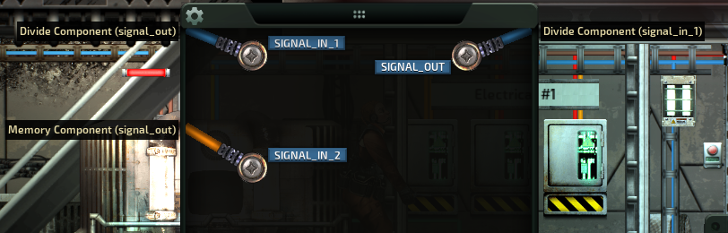
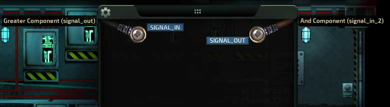
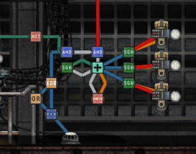
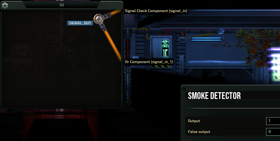
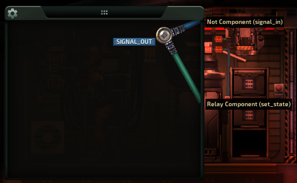
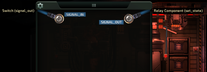
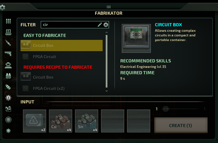
pretty sure that's cause converting to circuit box versions is self-explanatory... it's not like the actual circuit and components change or anything.
froggx 16 Jul @ 4:24pm 
dunno why i didn't notice this before, but last night i accidentally realized you can do "overcharging the shit" by low balling the value you enter into the memory output for (max reactor output/100). the reactor i was using had like 4000kW max and i got the engineer perk for +10% output but forgot to change the memory block from 40 to 44. later i noticed the reactor was overcharging everything by ~10%. if one desires a toggle then they can convert the memory component to a signal check and add an on/off switch.

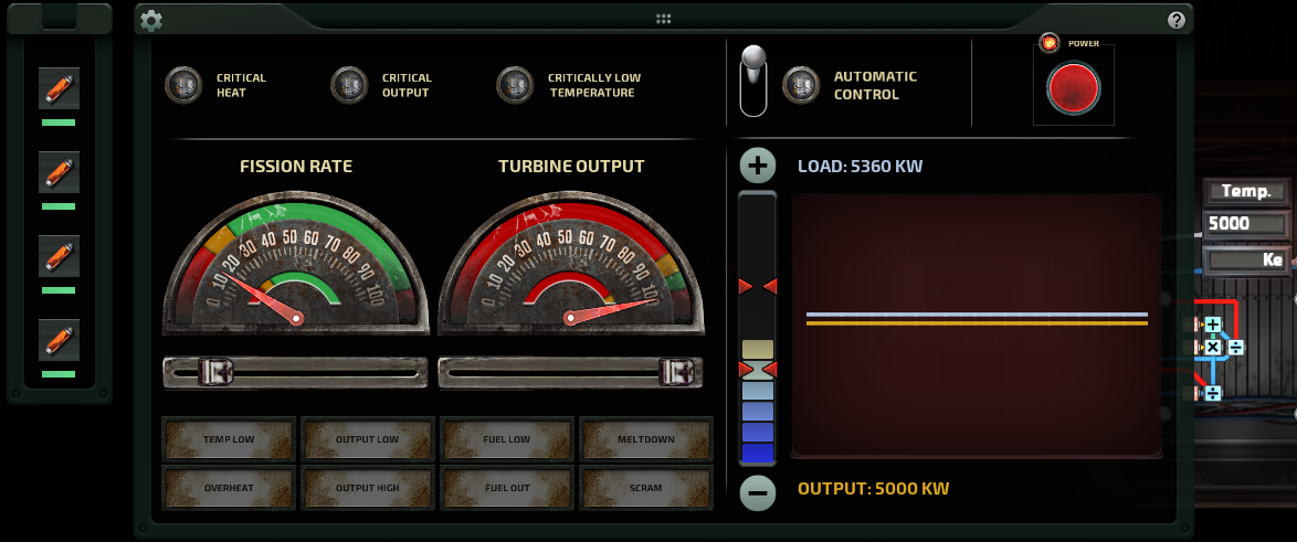
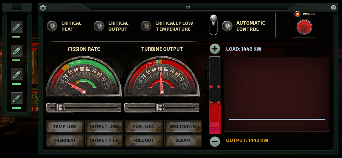
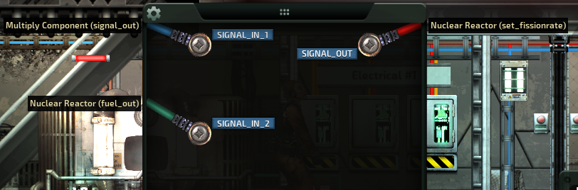
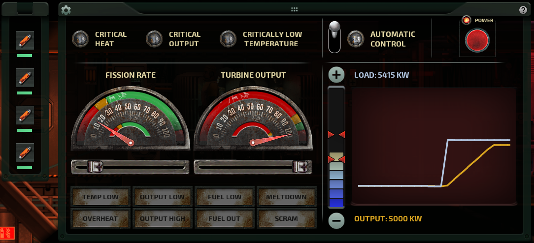
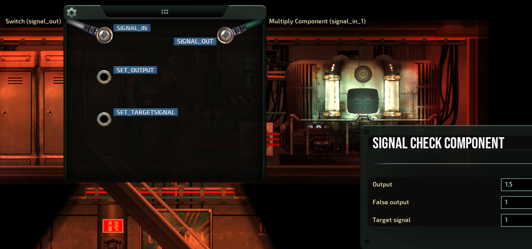
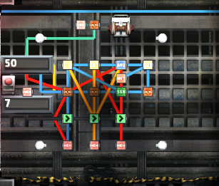
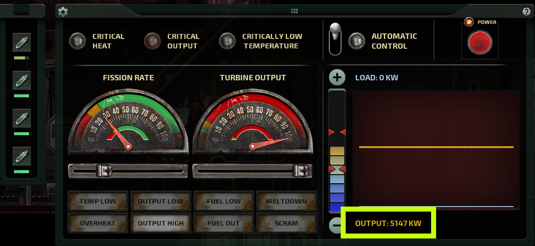
normally i do dynamic overcharge based on engine speed (ramming speed, bitch), but this time decided to just leave this accidental static ~10% overcharge in place cause it was so easy and required no extra components. i skipped the on/off switch cause i wanna burn up some fuel rods to make more hardened crowbars and screwdrivers.
Morricore 16 Jul @ 7:30am 
Impressive guide. It's a pity there is no circuit box version of reactor schemes.
Natsuki 8 Jul @ 10:22pm 
@froggx thanks a lot
froggx 8 Jul @ 3:00pm 
@Natsuki

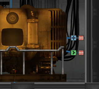
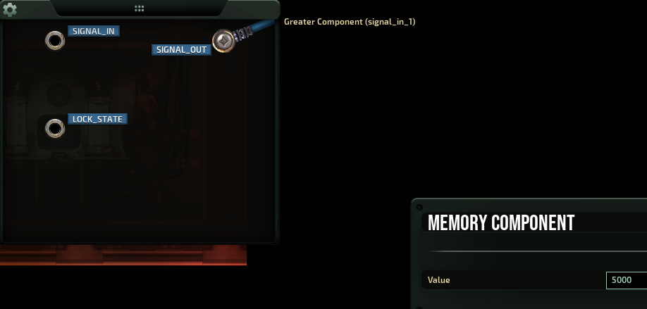
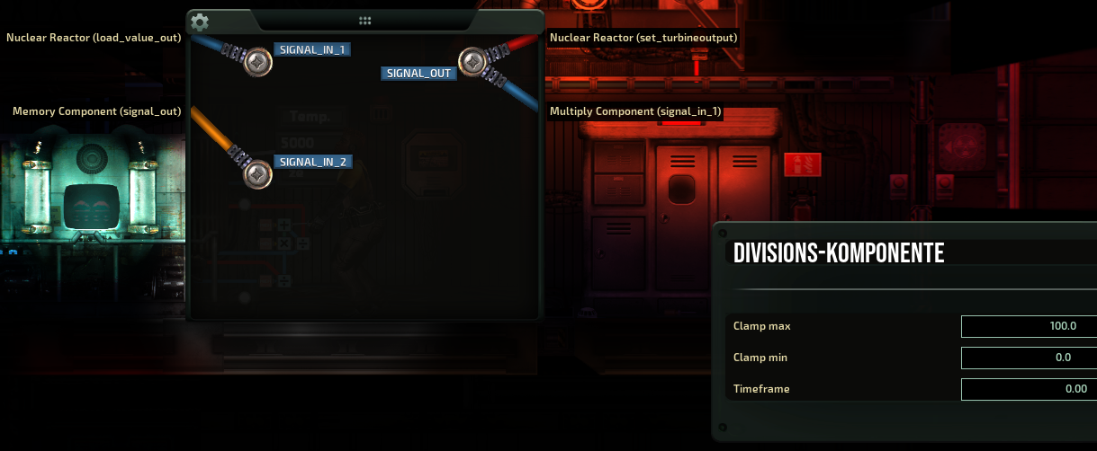
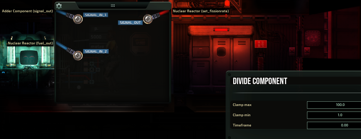
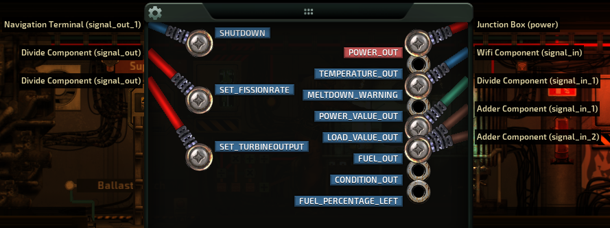
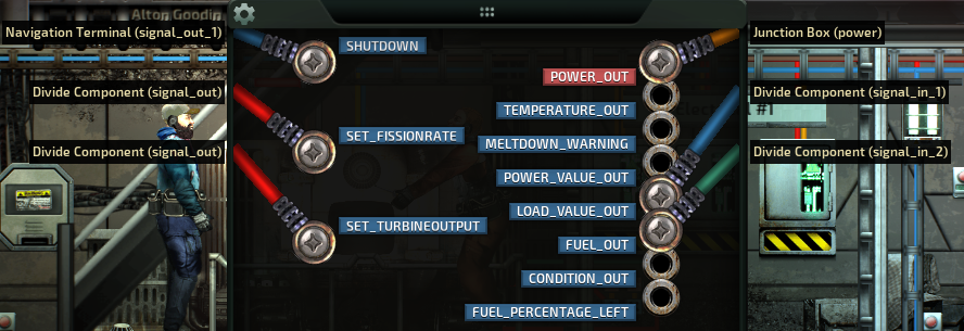
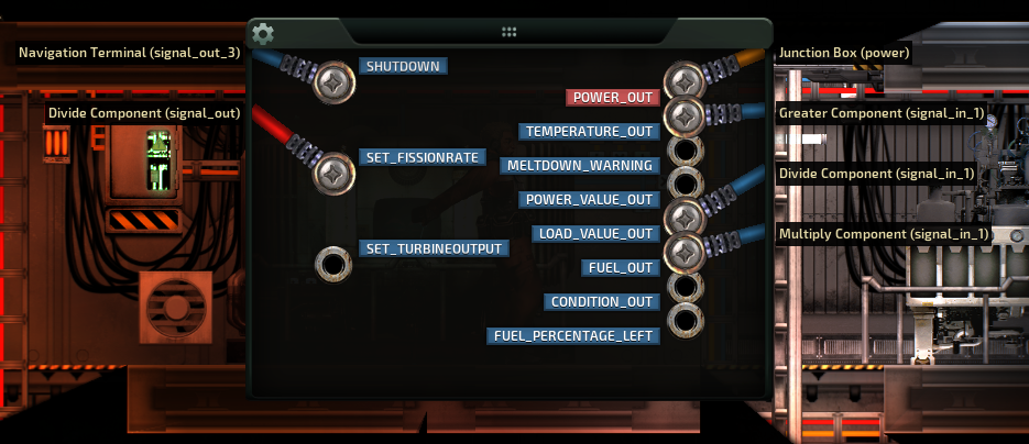
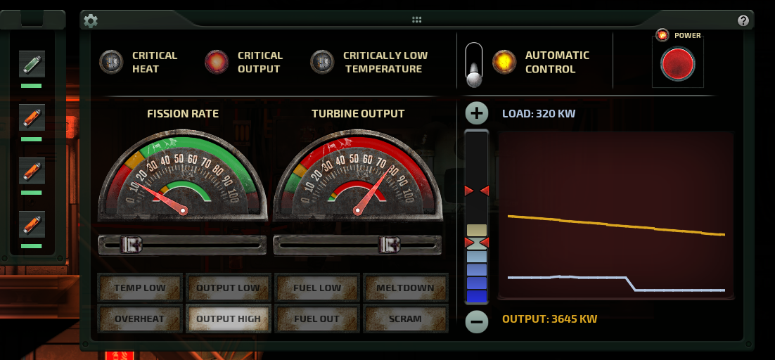
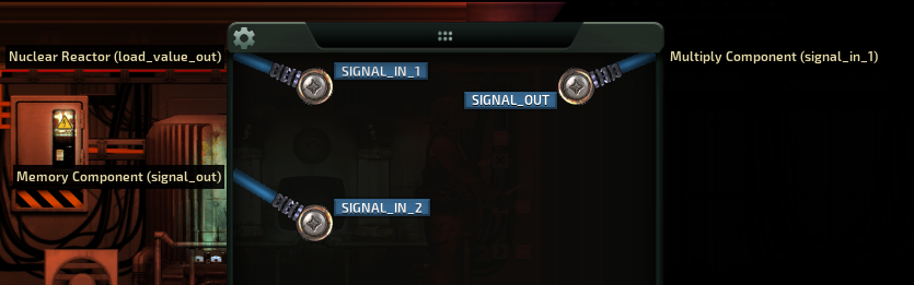
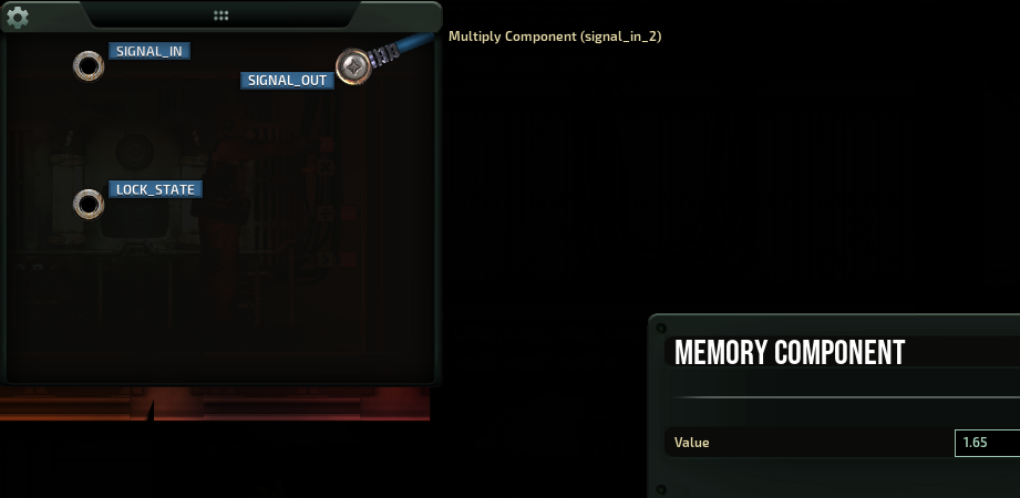
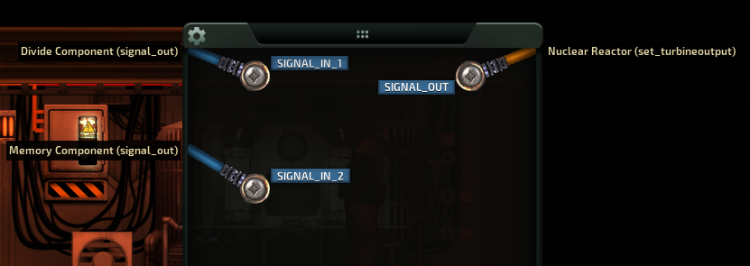
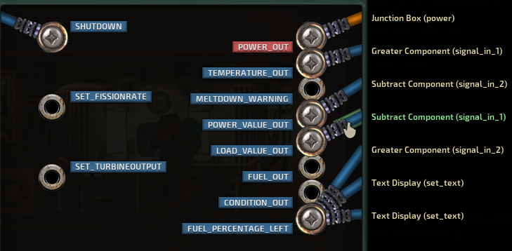
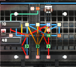
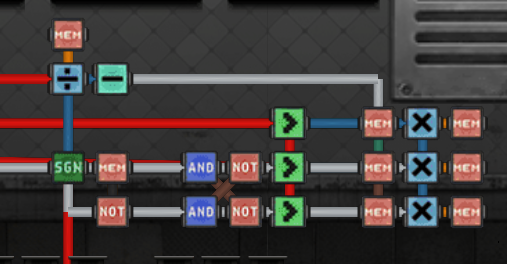
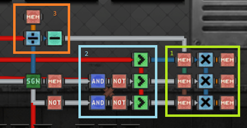
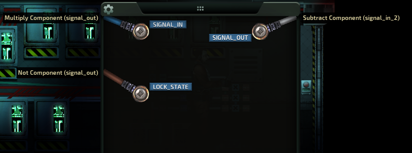
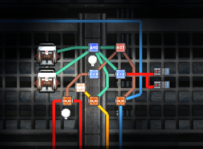
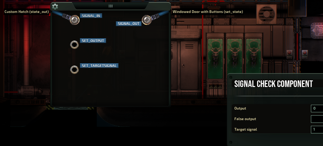
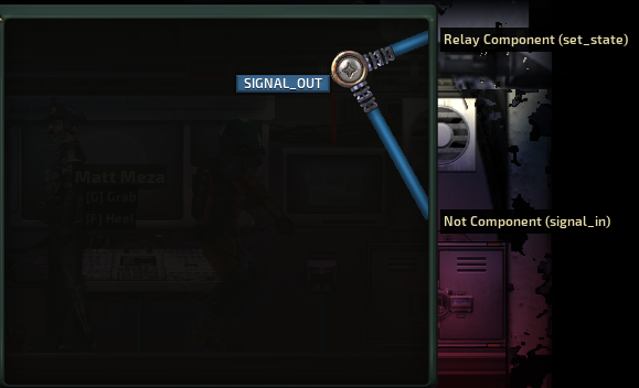
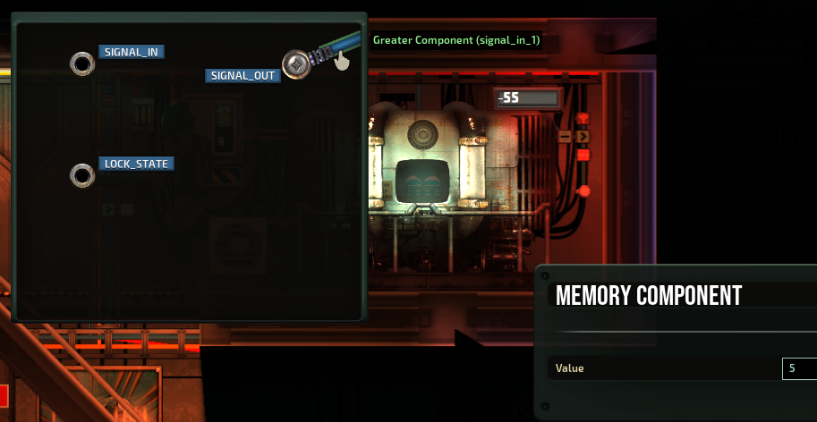
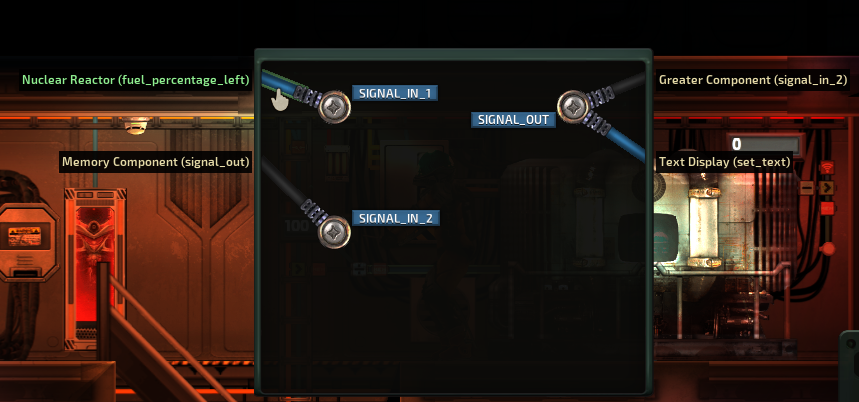
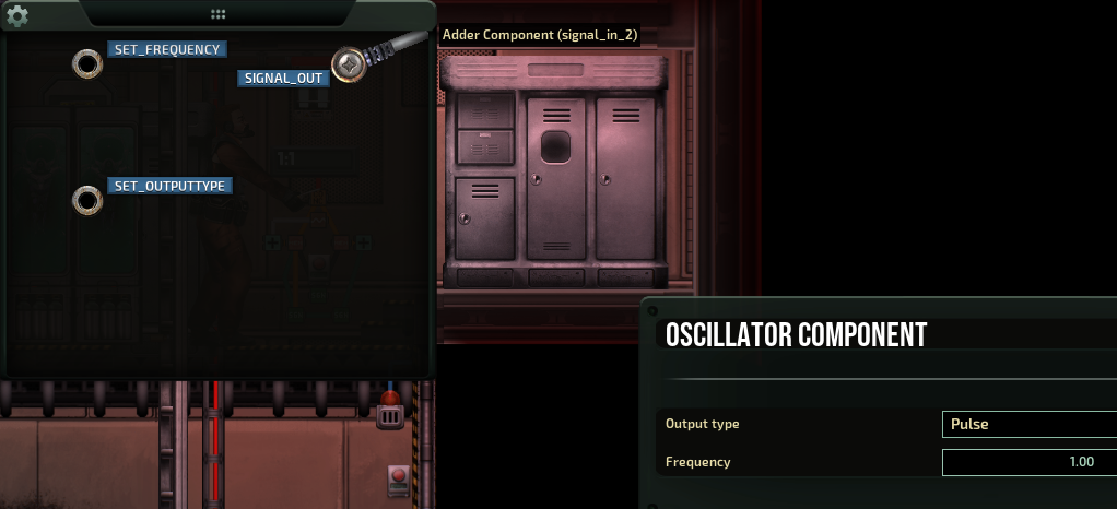
i recently started playing with hazardous reactors as well. the wiring diagrams that Qwerty has up here should work just fine. i can vouch personally for the efficient reactor controller being fine as i use a variant of that. i do something a bit different for overvoltage but there's no reason i see that the one up here shouldn't work.

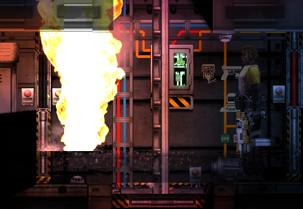
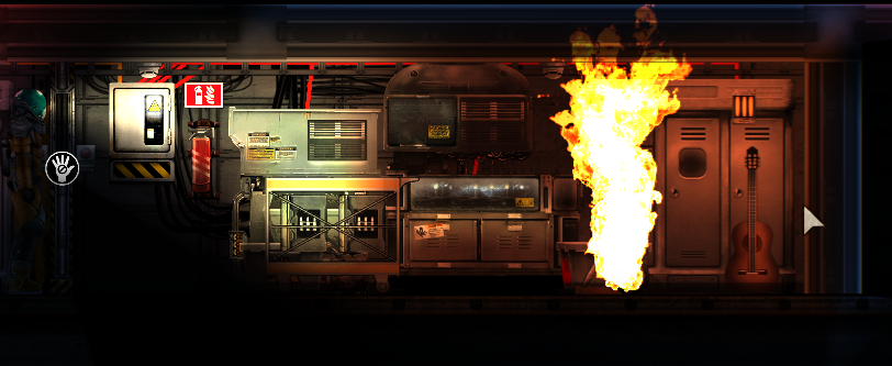
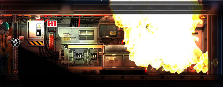
i'd suggest crafting a control rod and keeping that in the reactor just in case it overheats. while the reactor controller itself is pretty good about avoiding overheats, there's a glitch in the mod that has caused reactor fires when docking at outposts and the control rod prevents that.
Natsuki 8 Jul @ 11:37am 
hey im playing with hazardous reactors mod and im gonna use efficent reactor 2.0 and a overvoltage switch should i do any changes to controller
froggx 7 Jul @ 4:38pm 
@RedSpade

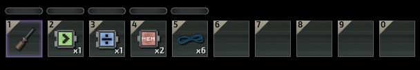
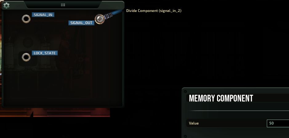
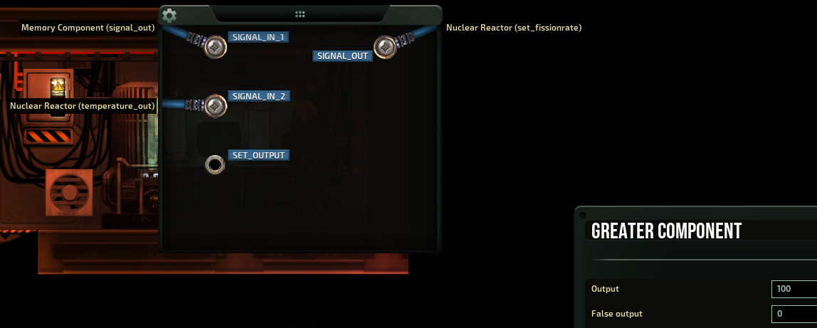
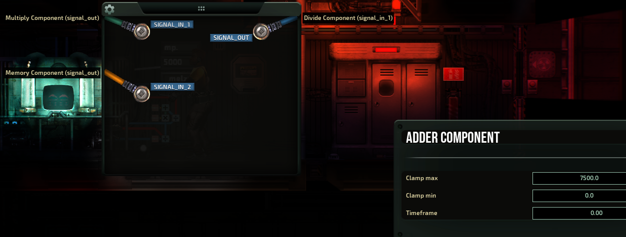
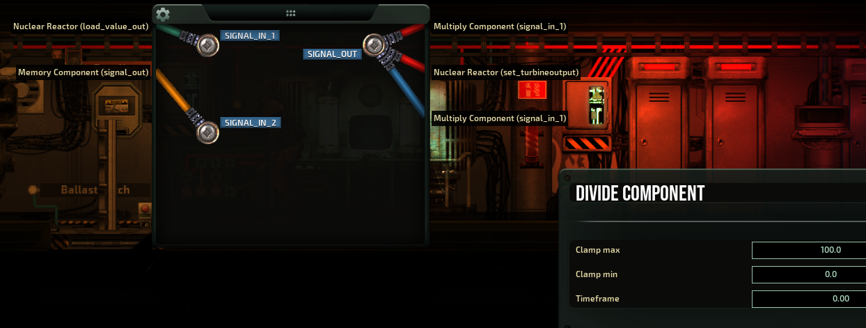
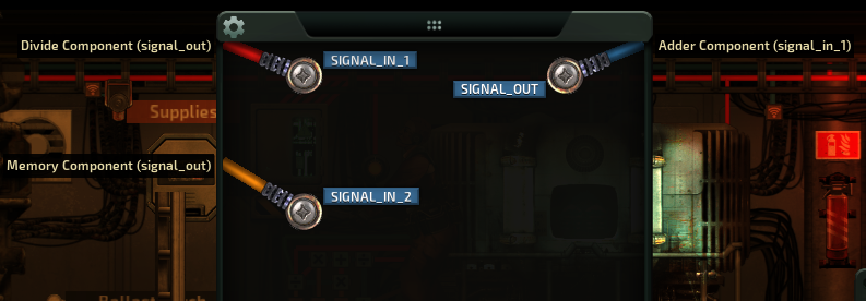
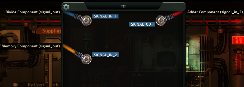
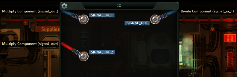
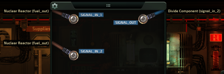
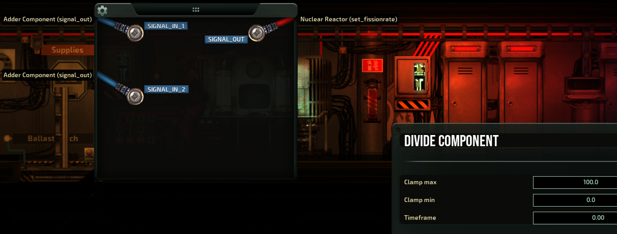
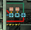
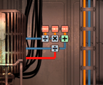
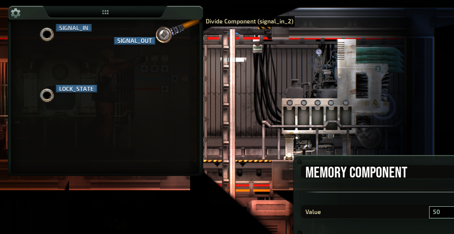
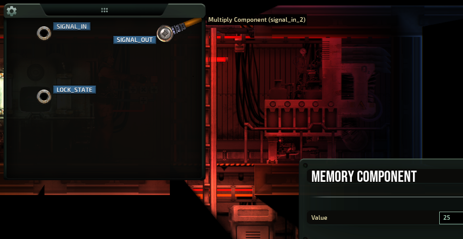
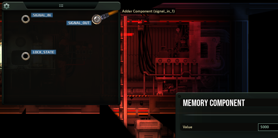
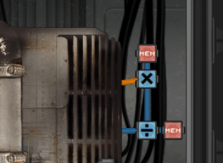
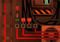
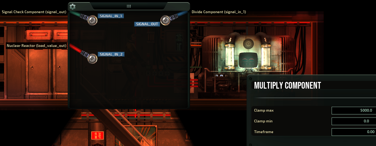
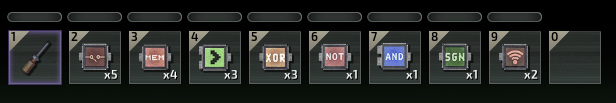
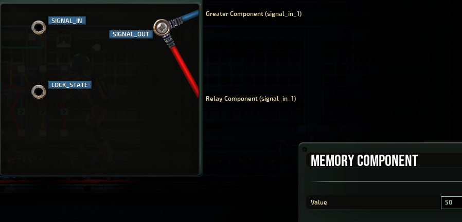
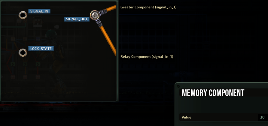
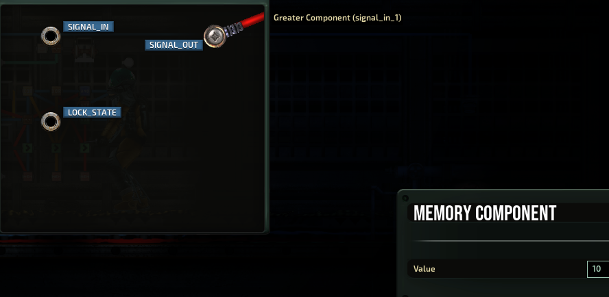
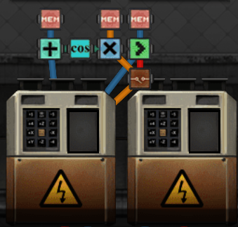
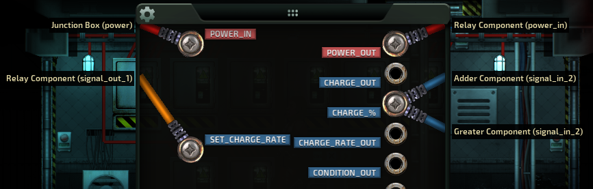
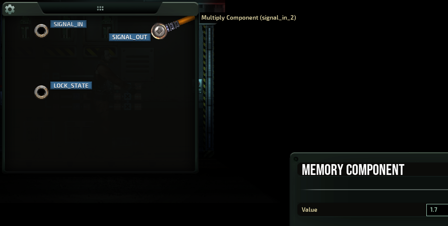
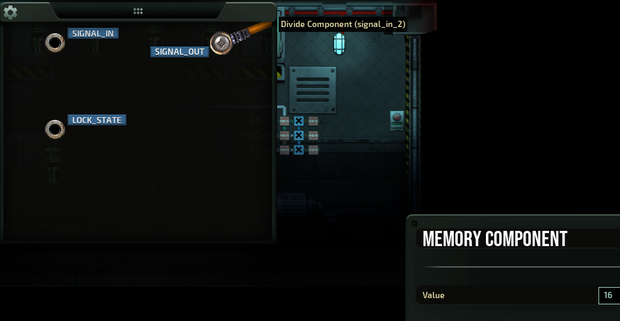
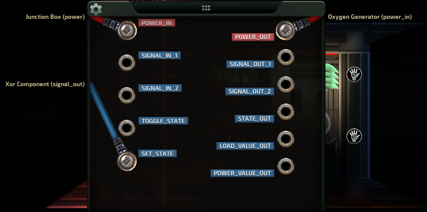
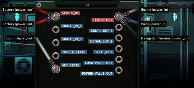
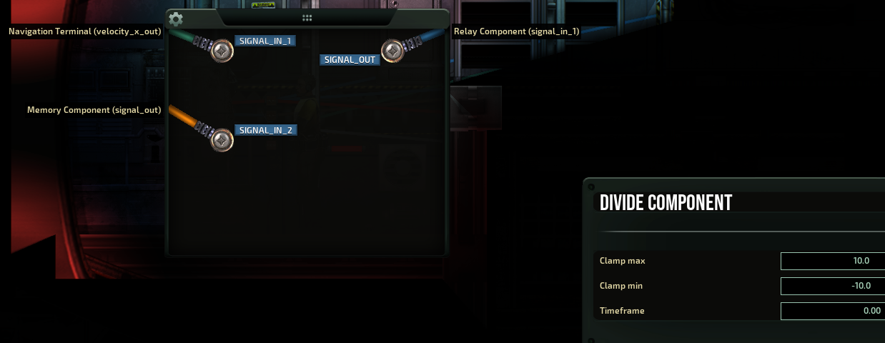
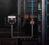
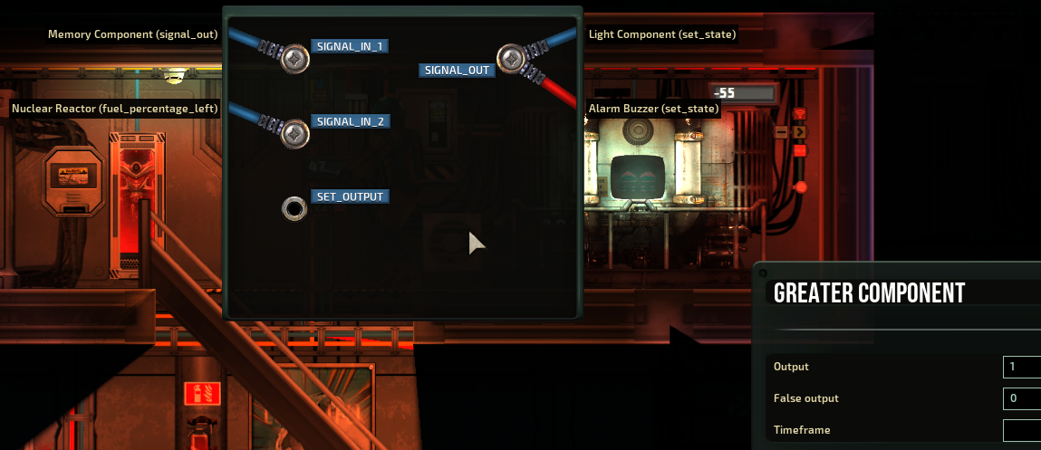
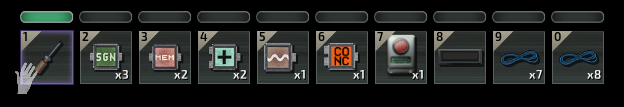
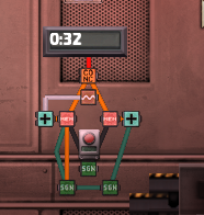
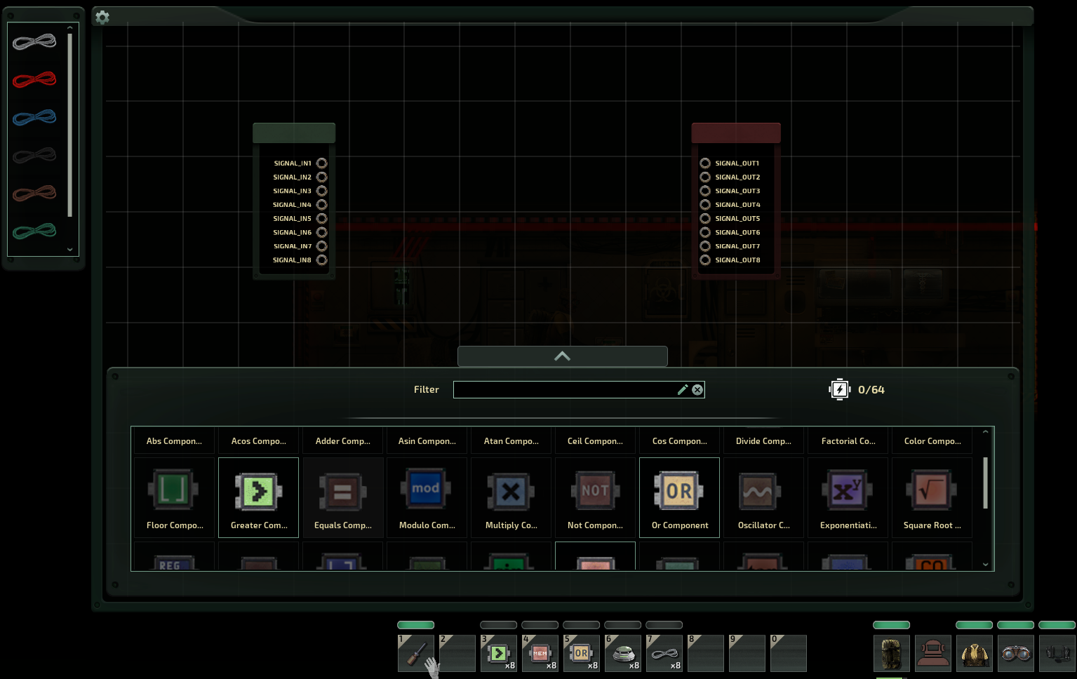
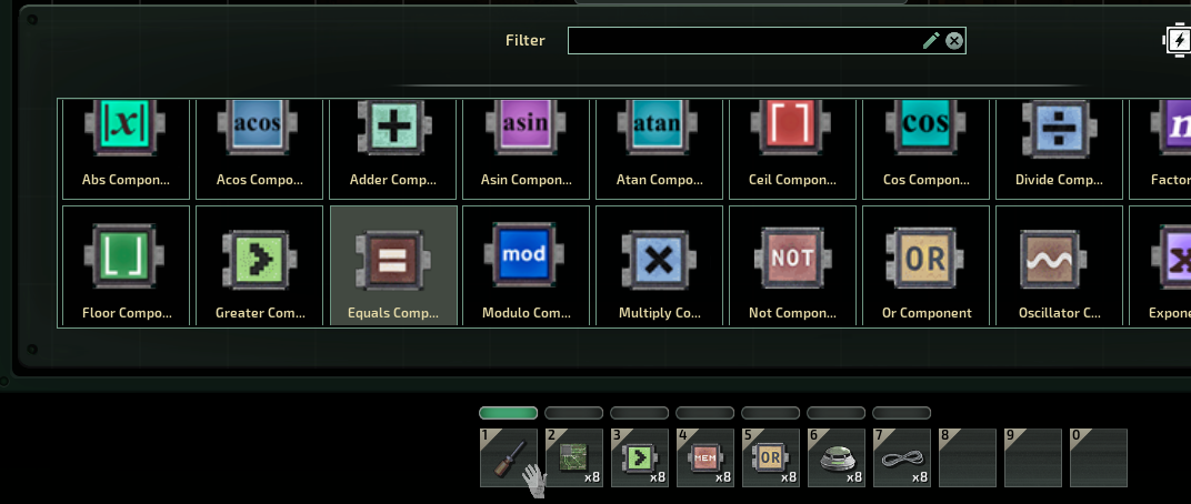
laziest way possible (aka full junction bypass) cause i can't do math to save my life :erune:

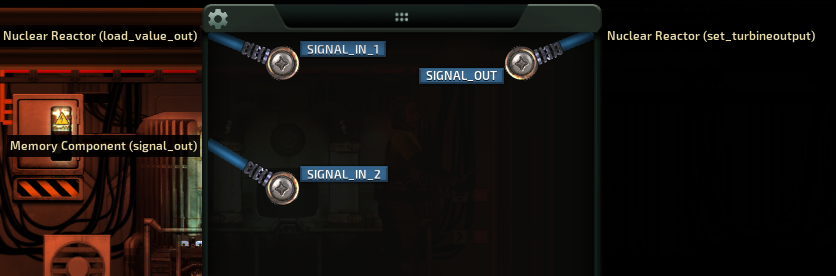
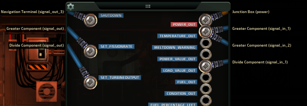
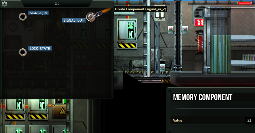
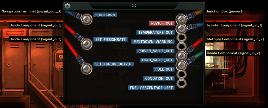
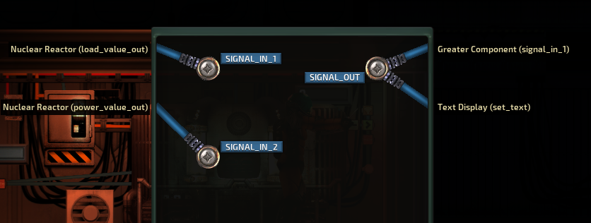
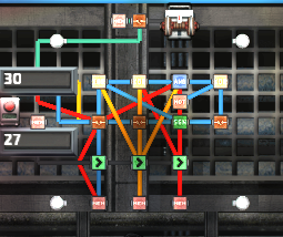
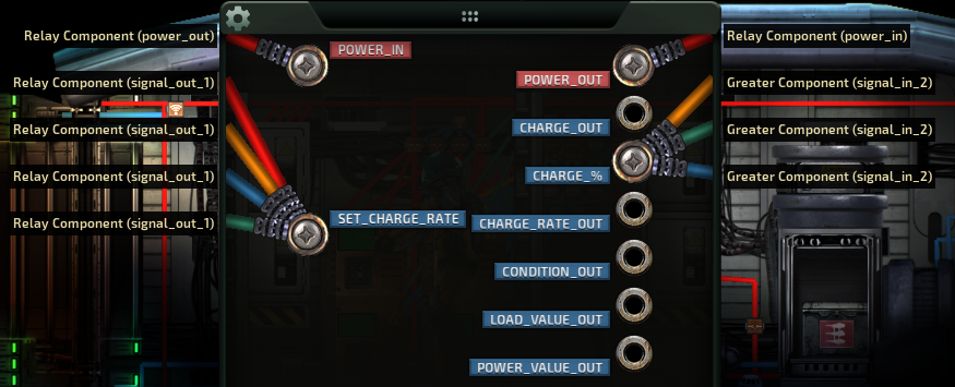
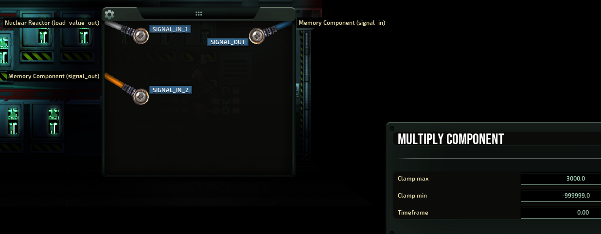
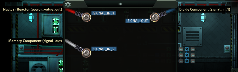
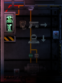
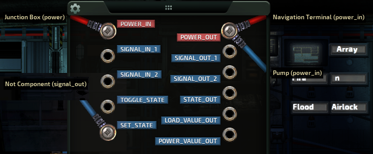
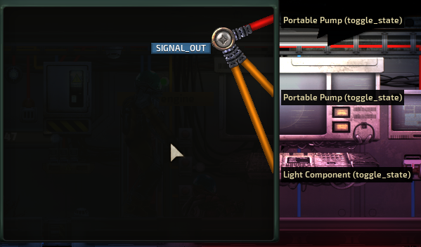
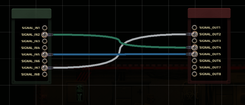
basically you can take the power output from the reactor and run it to the power input on the power distributor, which splits the single output from the reactor into 8 sub-outputs. normally the only things i have running off the junctions are batteries, engine, and constant loads (lighting, dive suit cabinets, etc)., everything else is either run off the batteries or a junction/battery split power thing, so it was easy enough for me to just move everything to the power distributor.

eventually i would like to do the math and put the junctions back in because it feels kinda cheap otherwise, but i'm currently playing an ironman campaign so i've had to limit my experimentation.
RedSpade 24 Jun @ 4:35am 
@froggx

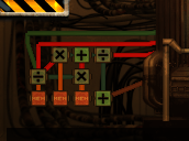
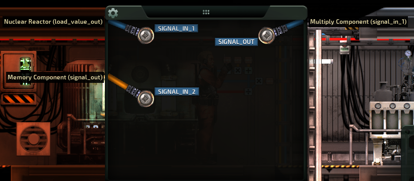
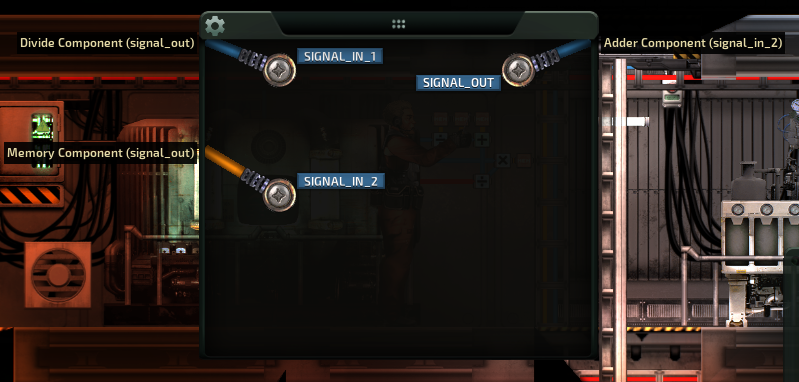
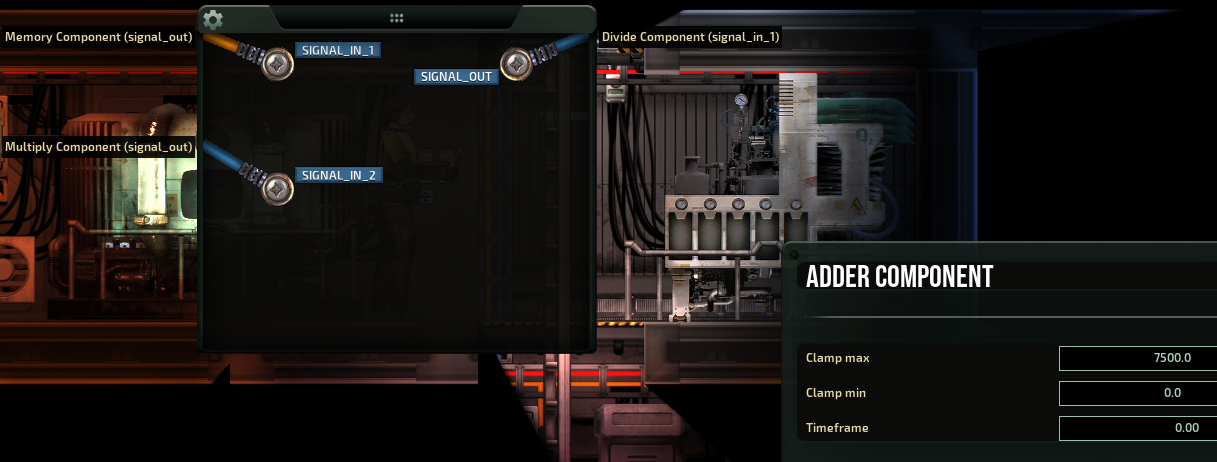
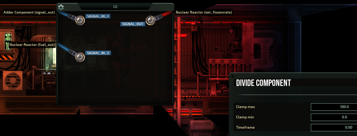
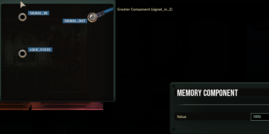
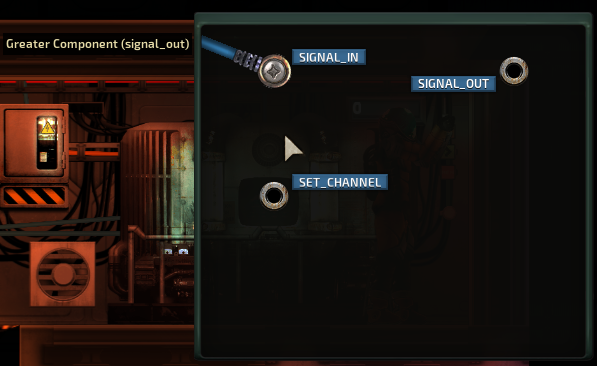
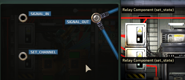
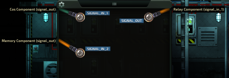
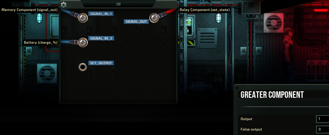
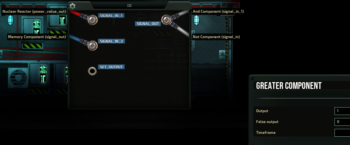
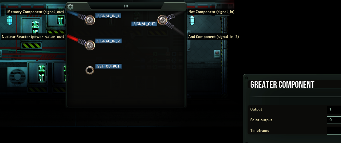
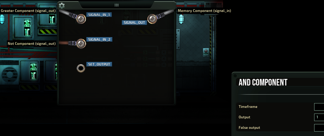
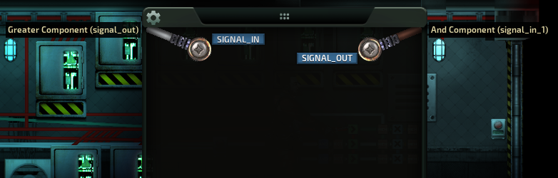
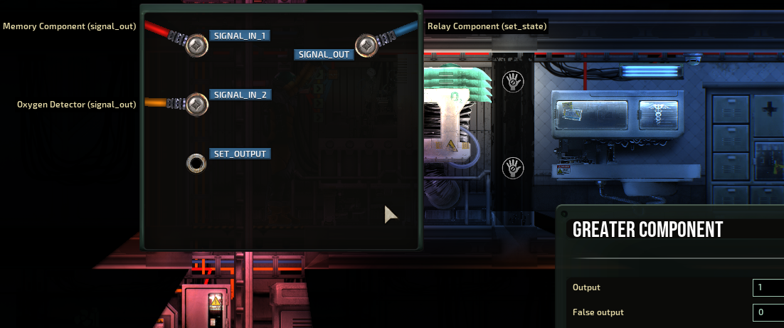
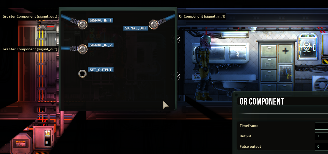
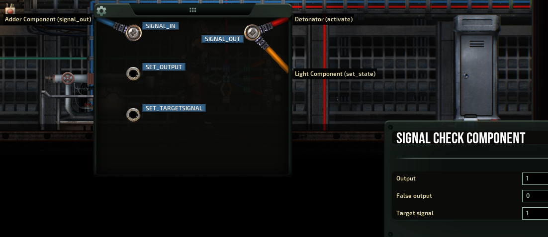
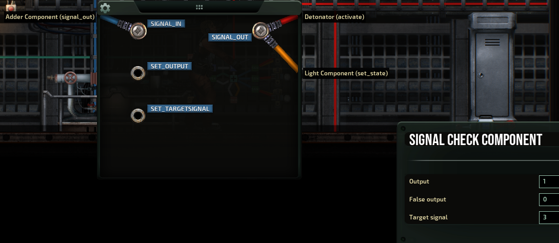
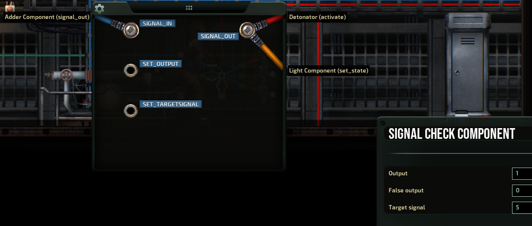
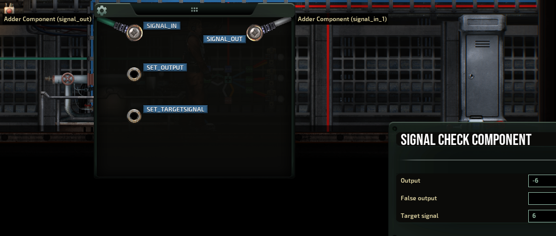
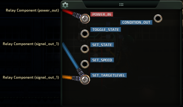
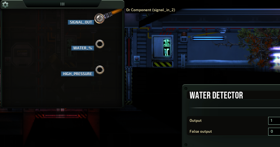
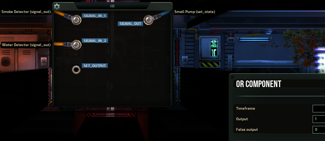
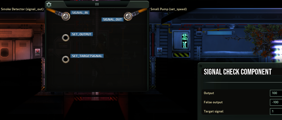
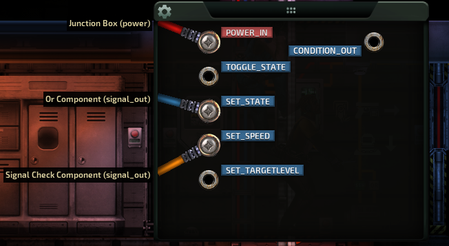
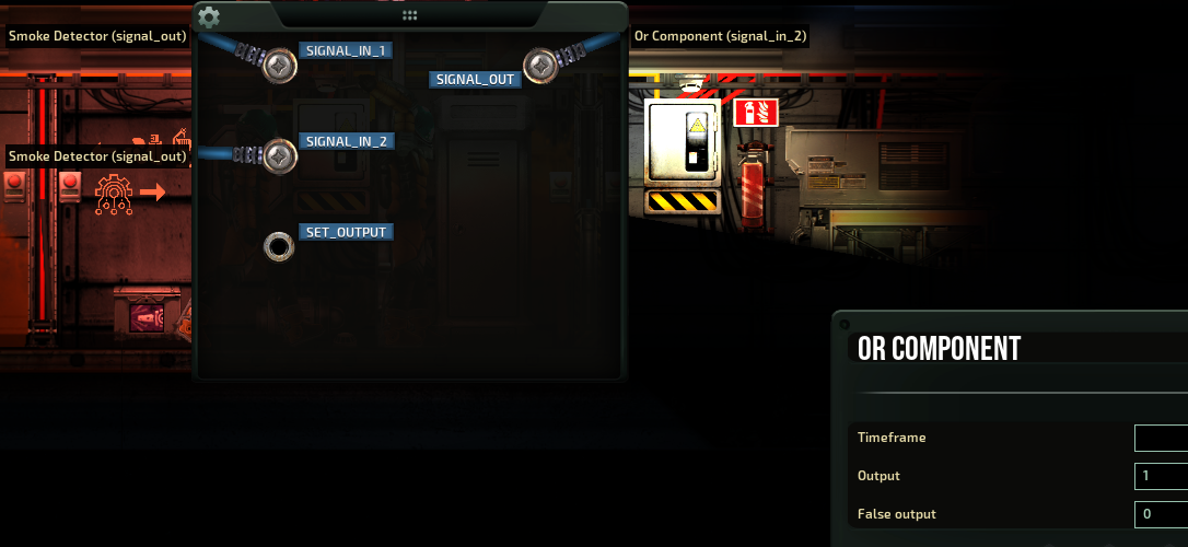
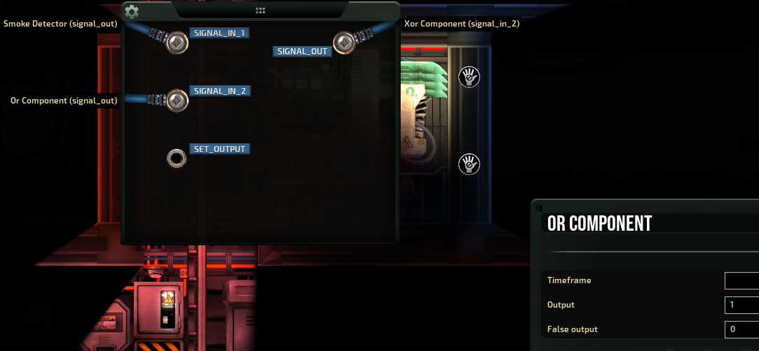
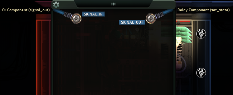
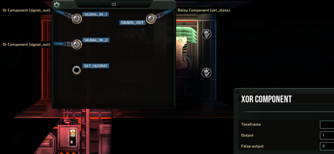
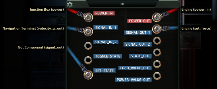
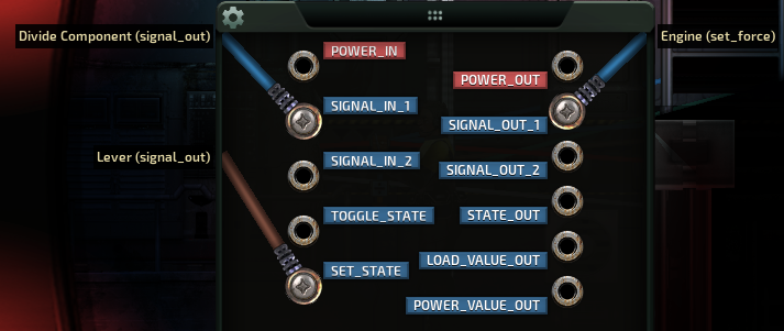
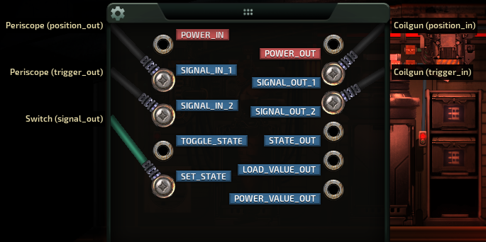
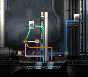
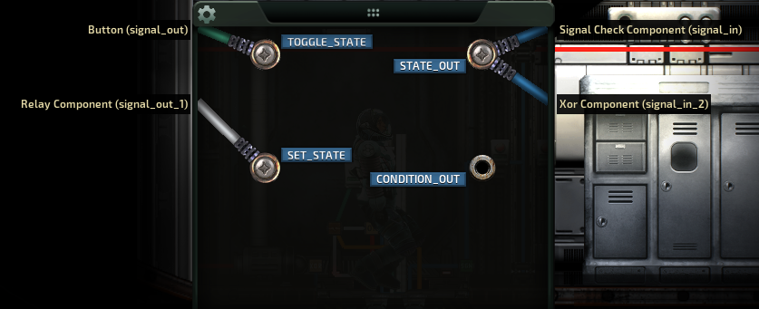
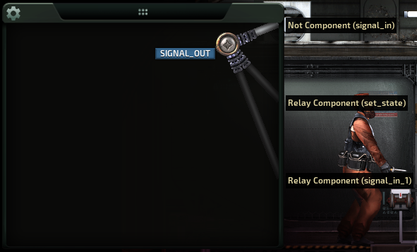
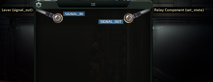
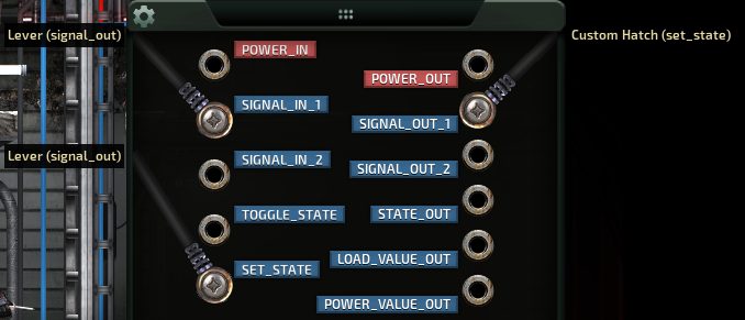
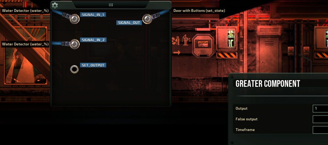
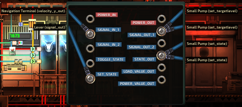
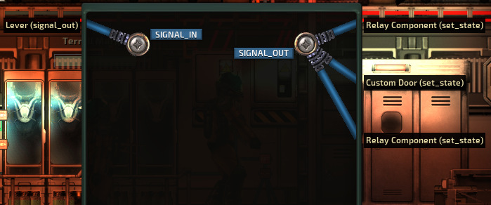
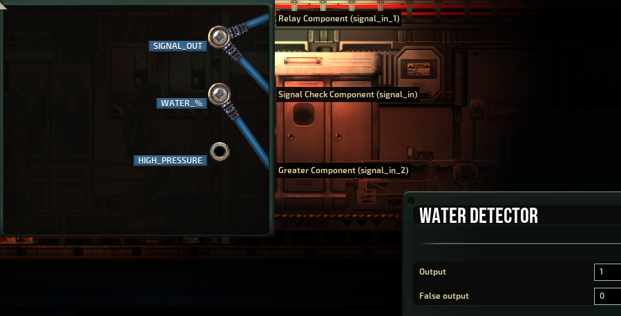
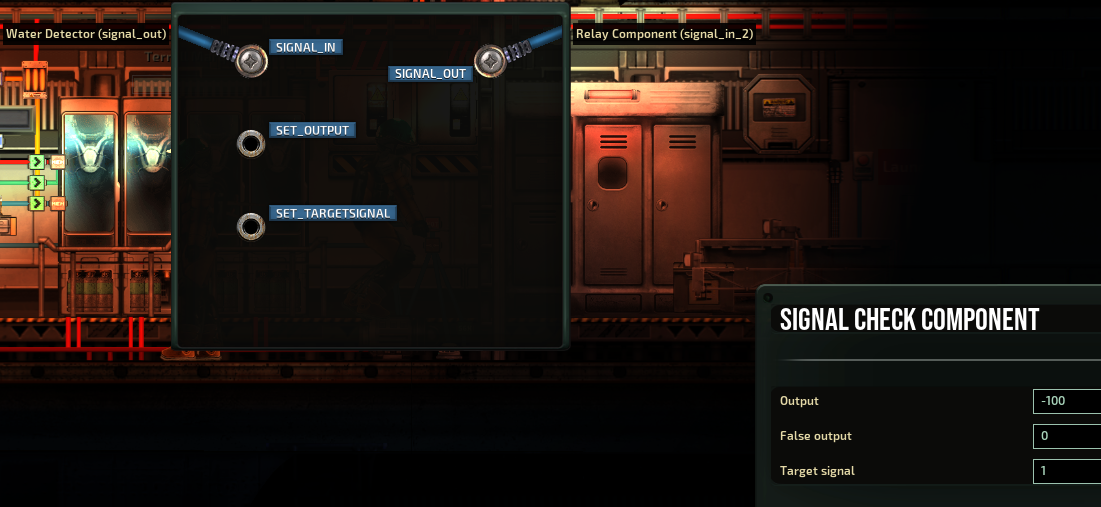
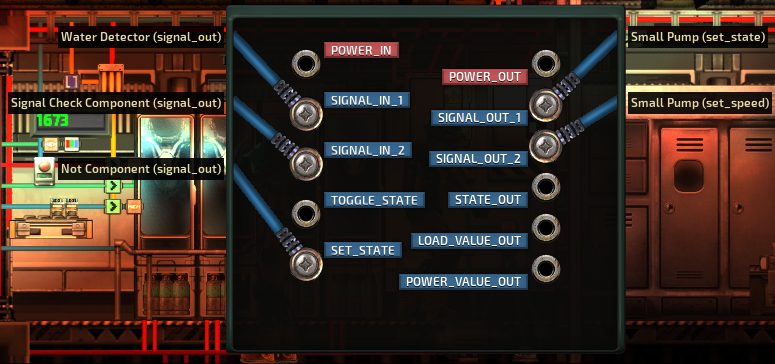
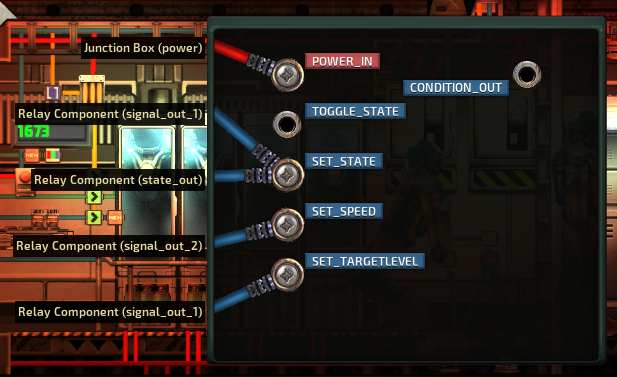
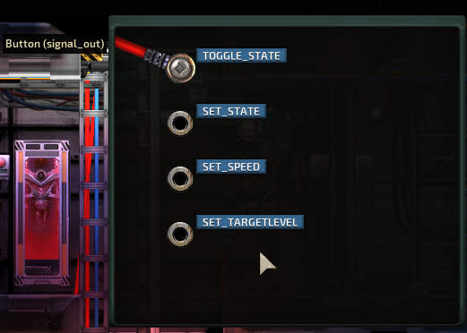
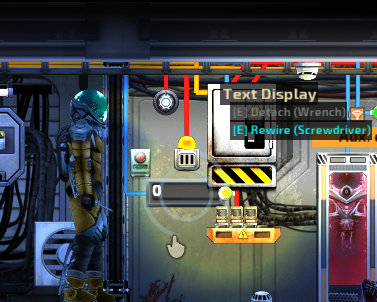
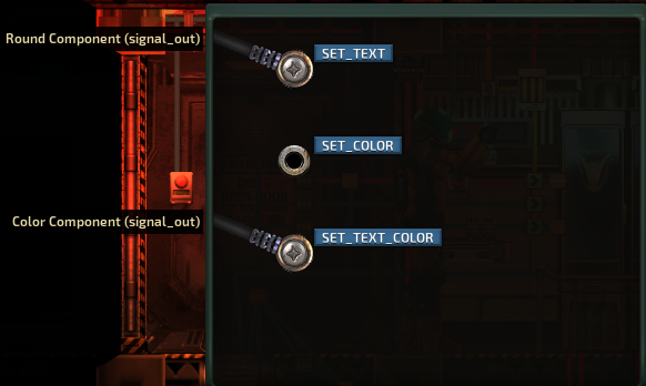
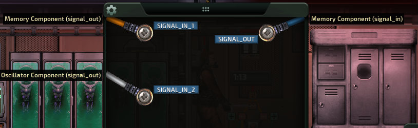
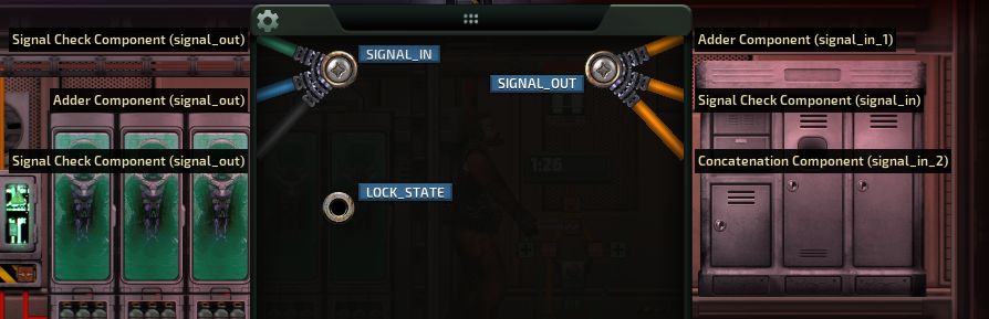
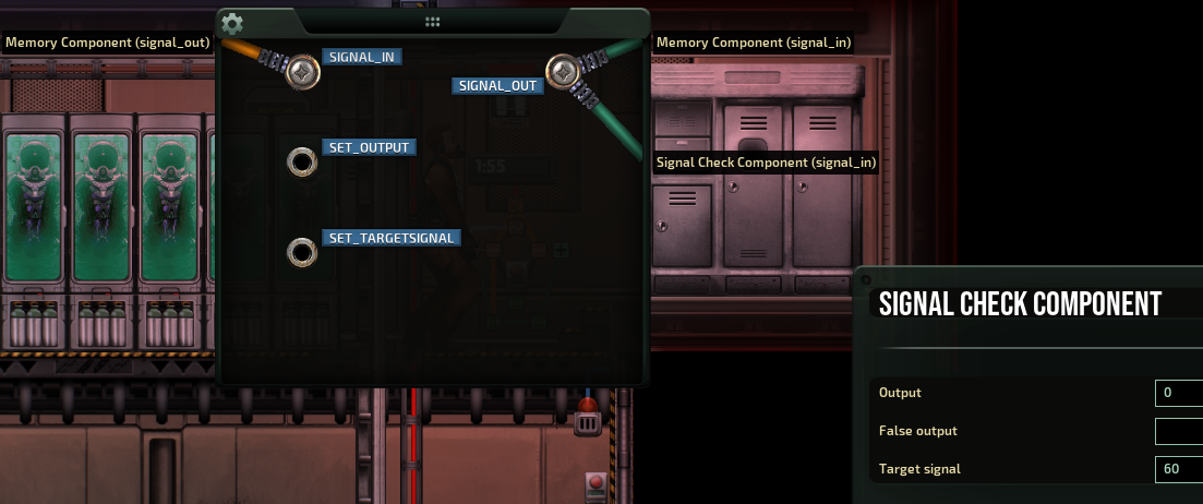
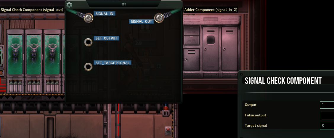
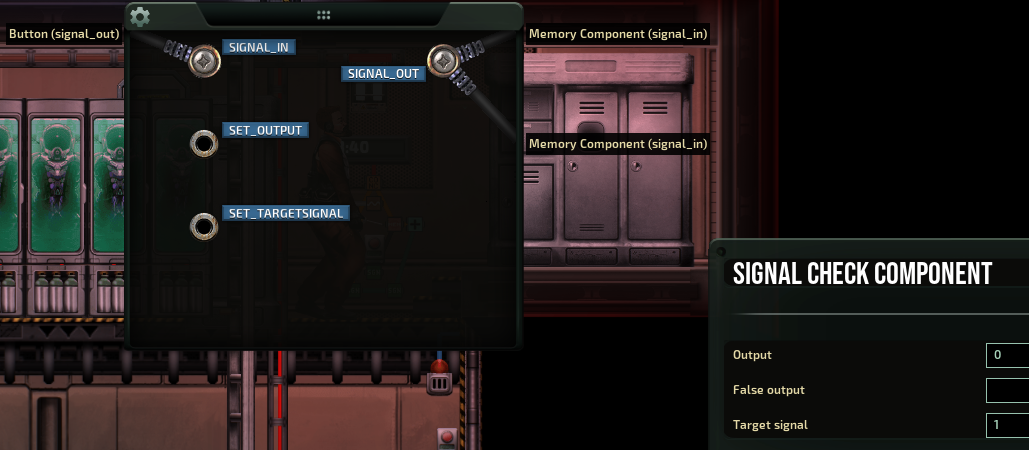
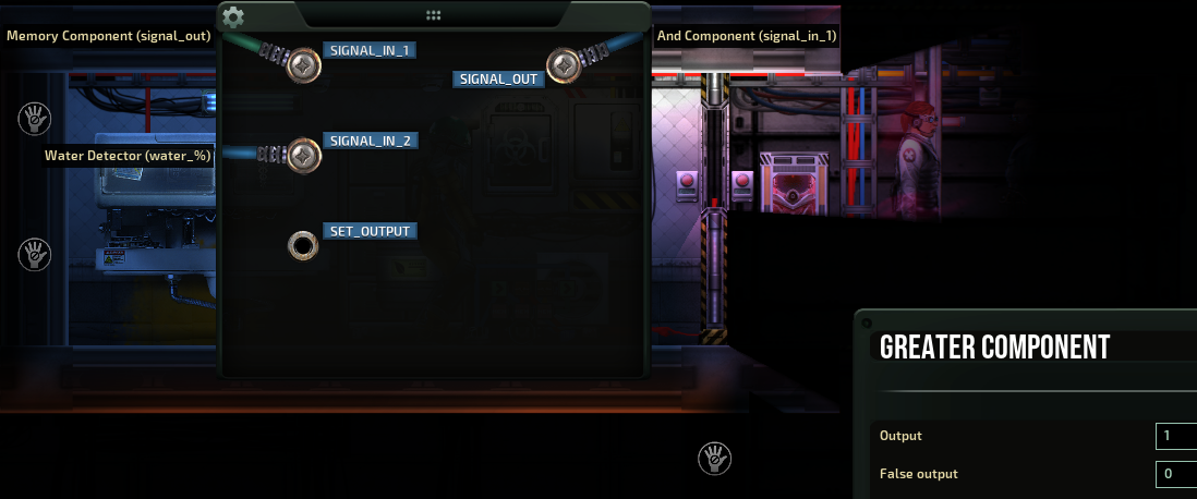
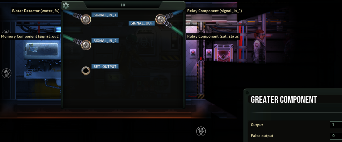
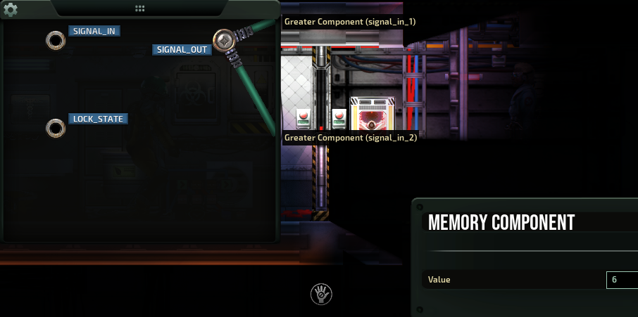
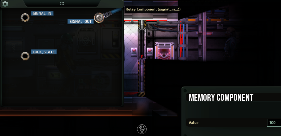
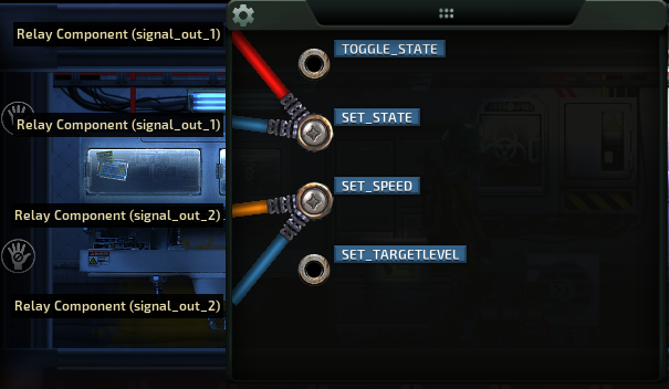
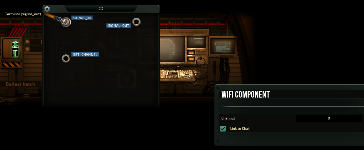
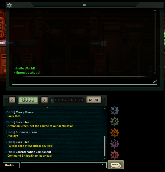
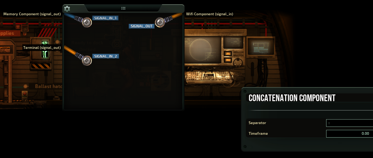
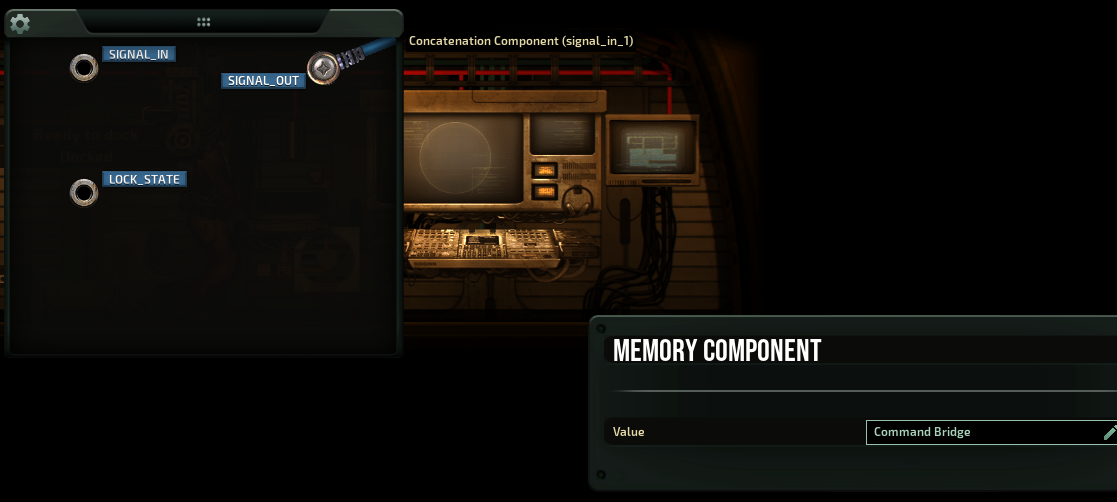
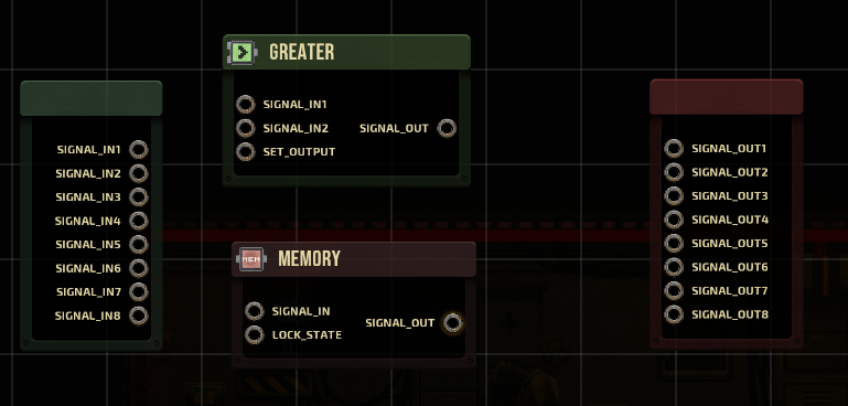
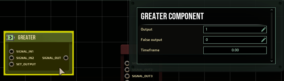
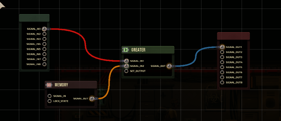
How did you wire it?
froggx 22 Jun @ 4:32pm 
not sure if you saw but they added a "power distributor" in the last update. this thing opens up a lot of new possibilities for power management. breaking the grid into "subgrids" just became quick and easy.

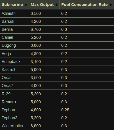
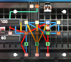
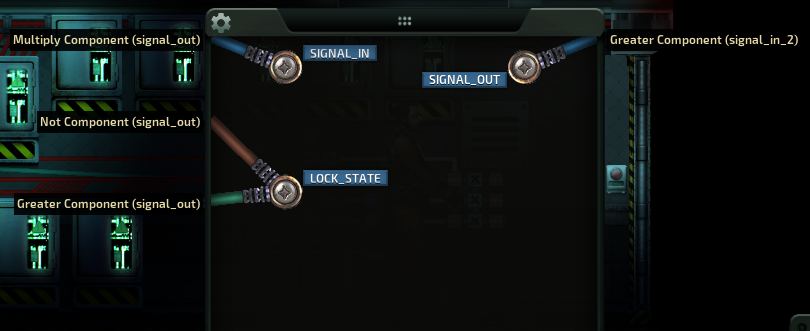
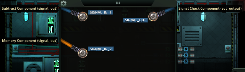
my favourite use so far is locking the reactor at max output and using some maths to prevent burning out the junction boxes by shifting power excess power to "overvolt friendly" components. it's a lot cleaner than previous methods to do so (like converting the engine to a PWM controller). best of all, doesn't make me feel dirty the way i do buying a barsuk just to harvest its cheat-level 5000kW relays :erune:
froggx 18 Jun @ 12:52pm 
coincidentally, on "pet friendly" subs i'll already have motion sensors on incendium grenades so that no one has to worry about their buddy "running out the airlock under its own power and definitely absolutely not already dead." it's a bit perverse, but people are way more chill when they can hold a proper burial, in ballast tank B, with the husked clown head and "that one security officer." i already try to keep pets by the ballasts tanks (burials go way faster), so that's covered too. tbh, this might be the first legit use case i've had for pets.

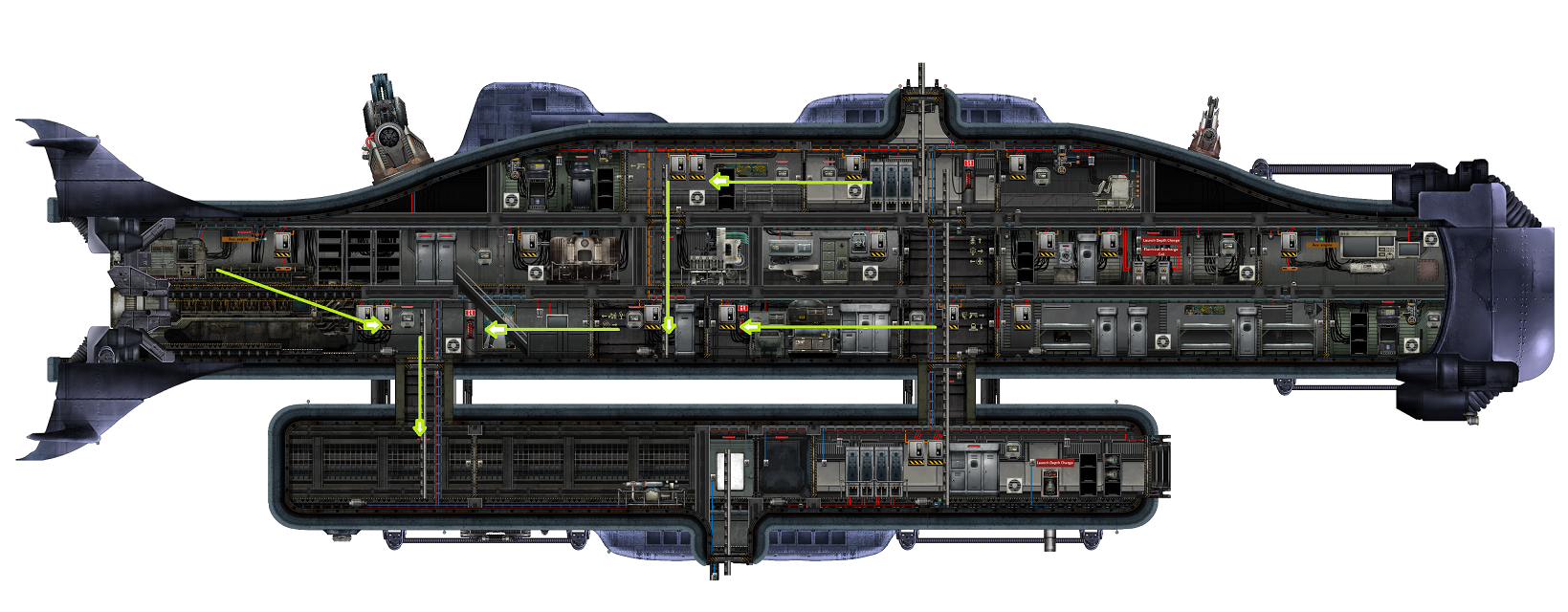
getting the water straight to the ballasts pumps really does make a world of difference though. a couple spots are no brainers to pop the hatches (right above the ballasts especially). i suppose it gets application specific very quickly though even things like our med officer compulsively hiring assistants matters; not enough dive suits and all.